Hey all!
I'm beginner with vacuum tubes and recently decided to build amplifier for PC speakers. On russian forums found simple schematic of single-ended amplifier with 6N3P (6H3P) and 6P14P tubes. I had all components and started to build it.
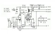
Components I have - 6N3P-EV, Tesla 6CC42, 6P14P and Tesla EL84 tubes, TVZ-1-9 (4,5kOhm, commonly used in soviet (russian) amps with 6P14P), cheap chinese no-name (5k Ohm 5W) output transformers and TS-180-2 power transformer from old tv.
After tests with chinese output transformers got -3dB at 70Hz and 2W. So decided to use TVZ-1-9 and got -3dB at 20Hz and 2W. Last one definitely sounds much better.
The measured voltage are a bit differ from original schematic:
- 6CC42 pin 4 120V,
- 6CC42 pin 2 - 1,5~1,43V,
- EL84 pin 7 - 247V,
- EL84 pin 9 - 6,2~6,7V,
- voltage drop over OT - 14V.
Anyway it all seems work stable, I already using this amp everyday for a month and very satisfied with sound compared to TDA2030A amplifier, that was built into PC speakers.
Yesterday I got idea to update my guitar amp, that built with TDA2030A too and sounds terrible.
I found few schematics with EL84 tubes and noticed that screen grid connected to HT with some resistor and in schematic I used earlier have it connected directly to HT. So in result I getting +263VDC at screen grid while ~ +250VDC at anode plate. After tiny research over forums and articles (most clearly described here The Valve Wizard -Single Ended) I found that screen voltage must be equal to anode voltage or bit lower.
And now I confused.
Is the original schematic have mistake there? Does screen grid must be connected after R8 (at my schematic) in series with 1k resistor?
Thanks
I'm beginner with vacuum tubes and recently decided to build amplifier for PC speakers. On russian forums found simple schematic of single-ended amplifier with 6N3P (6H3P) and 6P14P tubes. I had all components and started to build it.
Components I have - 6N3P-EV, Tesla 6CC42, 6P14P and Tesla EL84 tubes, TVZ-1-9 (4,5kOhm, commonly used in soviet (russian) amps with 6P14P), cheap chinese no-name (5k Ohm 5W) output transformers and TS-180-2 power transformer from old tv.
After tests with chinese output transformers got -3dB at 70Hz and 2W. So decided to use TVZ-1-9 and got -3dB at 20Hz and 2W. Last one definitely sounds much better.
The measured voltage are a bit differ from original schematic:
- 6CC42 pin 4 120V,
- 6CC42 pin 2 - 1,5~1,43V,
- EL84 pin 7 - 247V,
- EL84 pin 9 - 6,2~6,7V,
- voltage drop over OT - 14V.
Anyway it all seems work stable, I already using this amp everyday for a month and very satisfied with sound compared to TDA2030A amplifier, that was built into PC speakers.
Yesterday I got idea to update my guitar amp, that built with TDA2030A too and sounds terrible.
I found few schematics with EL84 tubes and noticed that screen grid connected to HT with some resistor and in schematic I used earlier have it connected directly to HT. So in result I getting +263VDC at screen grid while ~ +250VDC at anode plate. After tiny research over forums and articles (most clearly described here The Valve Wizard -Single Ended) I found that screen voltage must be equal to anode voltage or bit lower.
And now I confused.
Is the original schematic have mistake there? Does screen grid must be connected after R8 (at my schematic) in series with 1k resistor?
Thanks
Attachments
Someone described this to me before, probably DIYaudio member PRR.
Since B+ is at the "hot" end of the OPT, and the anode at the "Cold" end, the screen volts are usually higher than the anode, due to the DCR of the winding; and the fact that the screen tap is "nearer", less turns from the B+ end. Pretty normal.
My explanation why some schematics show a screen resistor is this: I guess that it is to act as a stopper resistor, OR to limit current.
Neither of these may be correct, hopefully if I'm dead wrong, someone will correct me.
I understand that output transformer will cause some voltage drop, and in my case DC resistance is about 260 Ohm so drop ~ 13V. But information, that I found at different sources points that I made something wrong here.
Is that 13V a "few" or not? 🙂
And do I need to lower B+ to 250V (by changing 200Ohm resistor in B+ to 400Ohm) to get 250V at screen grid and ~237V at anode plate?
Thanks
The transformer primary has very low DC resistance so only a few volts will be dropped across it, which we usually ignore. Therefore, the quiescent anode voltage will be the SAME as the HT, no matter how much quiescent anode current we choose.
Is that 13V a "few" or not? 🙂
And do I need to lower B+ to 250V (by changing 200Ohm resistor in B+ to 400Ohm) to get 250V at screen grid and ~237V at anode plate?
Thanks
... ... ... ... ... ... ... ... .... ... ... ...screen voltage must be equal to anode voltage or bit lower. ....
Huh?
These are not True Tetrodes.
And if Merlin says that in your link, I don't see it.
RCA once ran 6L6 at 150V plate and 300V screen.
Show me where it actually says this won't work.
Or try it.
In amp I made it works but I want to determine for myself is it correct or not.
In article I mentioned earlier stated that
Another discussion I found here Importance of Screen Voltage of Pentode??? with similar ideas.
Are there any source, book or article that have clear information about this? 🙂
In article I mentioned earlier stated that
andthe quiescent anode voltage will be the SAME as the HT
So I made conclusion that screen voltage must be (or should be for unknown reasons) lower that HT and so anode voltage.The screen voltage is usually set by a dropping resistor in the HT supply (Rg2)... This will place the screen voltage at roughly the same voltage as the anode, or a little lower.
Another discussion I found here Importance of Screen Voltage of Pentode??? with similar ideas.
Are there any source, book or article that have clear information about this? 🙂
The screen draws little current at idle - it has much less area than plate, so even if it's at a slightly higher voltage, the plate gets most of the current. Now feed some audio into the grid. The plate swings higher and lower than the supply voltage, and when it's LOWER, the screen attracts more current. Play a long full volume note on your guitar and the screen may overheat - unless there's a resistor limiting current. Most every guitar amp uses 470-1K wirewound resistor for screen(s). The occasional peaks of screen current in music won't average out to much, but instrument amps are different. The screen resistors will result in some waveform distortion - "compression" - but will help save output tubes.
What happens if you lower Vg2? You can't pass enough plate current to cover the peaks. What happens if you raise Vg2? You can pass more plate current than you need, but G1 drive becomes huge.
In SE A there is a happy value of Vg2 for each load resistance to get the most out of the tube. And the tube factories *wanted* you to know good operating conditions. In hi-fi and PA you won't go wrong plagiarizing the datasheet.
There are other happy combinations of parameters. 6146 at very high load impedance can be great at 600V plate 150V screen. But in audio a saggy Vg2 makes trouble. We usually prefer a single power supply so Vg2 can be near Vp and thus stable.
Screen is more sensitive than plate to power ripple (in unclipped duty). Therefore we usually like to take 5%-20% drop in a screen filter. Especially in for-profit work.
But sometimes the main B+ is already clean. For simplicity we take screen from there. The plate has the additional 2%-10% drop in the OT DCR. oh no! screen is lower than plate!! Relax. Is not a problem.
Thanks PRR, its clearer now.
So I thought it would be better to lower B+ to that "good operation conditions". Today added another 200 Ohm resistor to B+ and in result got:
- 250V at screen grid,
- 237V at EL84 anode plate,
- 13.2V drop over output transformer (DCR is 272 Ohm),
- 6,3V at EL84 cathode.
- 110V at 6CC42 anode
- 1,3V at 6CC23 cathode
So its looks like quiescent anode current now 48.5 mA, cathode current 52.5 mA, screen current ~ 4mA and all fits that "datasheet conditions". I see no difference in sound, maybe transformers not as hot as they was before after few hours of work.
But one new trouble appeared - now on startup I hear loud hum till B+ will get to 250V. Think because of anode voltage at 6CC42, it lover now and seems bias drifted down. Will try to adjust it back.
Attachments

- Home
- Amplifiers
- Tubes / Valves
- EL84 SE Amplifier Schematic Review