I would like to build Portable/battery headphone amp.
using 1U4, 3S4 or bigger tube.
Anyone knows the Schematic, no luck with google.
or bigger triode tube ?
using 1U4, 3S4 or bigger tube.
Anyone knows the Schematic, no luck with google.
or bigger triode tube ?
I don't think you will be happy with a 3S4 "final". Notice the high open loop harmonic distortion figure.
The data sheet doesn't get into intermodulation distortion (IMD), but 90 V. on the plate and 67.5 V. on g2 will yield the lowest IMD of the "typical" operating configurations.
The 3S4 is a LOFI portable AM radio tube. My dad had such a set. Multiple "D" cells were used to energize tube filaments and to bias the 3S4's control grid.
Does this need to be a tube amp or are you open to a hybrid design?
I would consider pairing a korg nutube with some jfets for a portable tube amp.
I would consider pairing a korg nutube with some jfets for a portable tube amp.
I am also looking for a portable battery powered full tube headphone amplifier. On my requirement list, "portable" means a device with the weight and size of a small laptop, maybe with a flat form factor to fit easily in a computer bag or backpack. Modern high capacity lithium batteries are small, lightweight and may have almost any shape, but output transformers cannot be miniaturized. I have already breadboarded two different single ended designs; both of them mains powered because the portable chassis and battery power supply design is a non-trivial task. I will tackle it later, if I will be able to get a working amplifier design with good enough quality.
The first prototype I've built does use a DAF96 voltage stage, DL91 output stage and a 3W output transformer with nominal 5K primary. I also tried 3V4, DL96 and 2P2P output tubes, with the correct polarization required by each one of them according to datasheet. Eli Duttman already summarized the major drawback of this design: high distortion. It is not nasty, some people may even like it, but it does not suit my needs. I believe that the flaw can be solved with global feedback; but then an additional amplification stage will be useful due to the low output of portable DACs and sources. A further issue is the size and weight of the required output transformers. I was unable to find a small enough Hi-Fi quality transformer. On the plus side, this type of direct heated triodes does have instant turn-on, like a solid state design. I can post the schematic, if anyone is interested. It can also drive a speaker at background music level. This design could easily be adapted for subminiature directly heated tubes; but issues would be the same, I believe.
Next, I've built a single ended amplifier with 6AK6 output tubes and 12AT7 driver tube. I actually used two PC92 single triodes: PC92 is exactly one half of 12AT7 / ECC81. Total filament supply power is almost 4W, high but can be managed by a battery. I used a 180V anode supply; it may be produced with a DC/DC step-up module. The major issue here is (again) the output transformer. I tried Hammond 125ASE but I was unhappy of the results. It sounds OK-ish, but not good enough. Better transformers are too bulky and heawy. I will resume this project when I will be able to find a small single-ended high quality output transformer, of if someone will come up with a clever trick to get the low-distortion goal.
There is a Mullard push-pull design with low-power ECL80 tubes that seems to be promising. It has been published on the second issue of "Mullard valves, tubes & circuits" and implemented on some British TV sets in the '50 (Ferguson 989t, as example). Has been further developed and described on the april 1957 issue of Radio Constructor magazine, and later on the August 1984 issue of Television magazine. The total filament power for a stereo build would be in excess of 6W, and this will definitely require a 5000 - 8000 mAh 7.4V LiPo battery, the kind used on RC helicopters. The weight of this style of battery is 250-300g but the power density is very high. Typical values are 200Wh/kg.
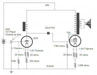
Here is an amp my son built for a science fair. We tried to generate B+ with a huge array of potato, lemon, or combination or both batteries, not entirely successful, well not successful at all. With traditional batteries it worked fine. The output transformer was an old Radio Shack #32-1031B, choke was Hammond 156C.
I don't know if your goal is small or just battery. For small you may want to try Russian subminatures like, 1J17B, 1J18B, 1J24B, 1J29B all DHP. 1S38A and 2S14B are DHT. Then there are U.S. tubes like 5676, CK512AX, 6088, etc.
Stevie Bench has a variety of battery suggestions <http://diyaudioprojects.com/mirror/members.aol.com/sbench101/#Battery>
Edcor XSM or similar work fine as series outputs if plate current is under 3ma, as do most small distribution transformers. Battery powered amps come up regularly on this list so search away.
Matt
Attachments
My goal is triode headphone amp battery.
Triode means real audio tube like “45, 2a3, 300B” sound quality.
6as7 is a good sample but impossible to use battery that last long enough.
Maybe similar tube but smaller than 6as7.
Nwibie, that 1s4 schematic I think is to weak to drive headphone, I’m thinking bigger output than 6as7.
I think the key is to find the right tube.
Which headphones do you want to drive? I have used the 3S4 as a transformer coupled headphone amp, but output was very limited.
Recommended power is 250mW for something like the LCD2 and it's a 70 ohm headphone. That's 4.2V RMS. If we assume that you order a 10K:70 output transformer to go with the 3S4, that means a voltage step-down ratio of 12:1, so you'll need to swing 50VRMS at the plate of the 3S4.
50V RMS is 70V peak, the max plate voltage is 90V. Since there's a hard stop on the plate curves where the 0V grid voltage line is, we can conclude that delivering 250mW is pretty tough with the 3S4.
I would suggest using a different set of headphones or not using batteries.
50V RMS is 70V peak, the max plate voltage is 90V. Since there's a hard stop on the plate curves where the 0V grid voltage line is, we can conclude that delivering 250mW is pretty tough with the 3S4.
I would suggest using a different set of headphones or not using batteries.

The weight of batteries and magnetics is a major issue. The end product is luggable, not portable, as in "Walkman".
FWIW, adequate power O/P of approx. 750 mW. could be obtained from a PP 3S4 pair running under near Class "B1" conditions. Put 99 V. on the plates and 67.5 V. on the screen grids. A 15+ V. cell stack plus 4X trim pots. would be needed for 3S4 g1 bias. Also, 2X "floating" 1.5 V. cells, with their - terminals connected to pin 5 and their + terminals connected to the filament's ends, are needed for each 3S4. Can you say A, B, and C batteries galore?
Power up for such an O/P stage requires careful sequencing. 1st, activate the bias supply. The bias supply needs to be switched to prevent discharge, when the unit is not operating. When operating, a small current is present in each trim potentiometer. 2nd, activate the filament supplies. A switch pole is needed for each of the 4 O/P tubes. Fortunately, the B battery does not have to be switched, as it experiences a draw only when the tube filaments are hot.
The small signal circuitry needed to feed such an O/P stage is "a can of worms" that, for now, I will not address.
IMO, the OP's desires and practical realities are not congruent. 🙁 Sorry.
most good headphones are 250mv recommend power.
For batteries, you're going to constantly hit the same wall unless you use multiple tubes per channel.
I have never heard that most good headphones need 250mW.
You should be able to get 150mW from a 1S4/3S4 triode-wired, running 90v at 6mA quiescent into 6.2kOhms - pure SET. It's actually quite linear in triode mode - see the Sylvania data sheet. Probably you'd need a custom output transformer.
The Sylvania datasheet employs the conservative design center rating system. A single "10"% liberty should be OK. Push UAK to 100 V. and tie g2 to the plate with a 470 Ω current limiter and a 150 mW. power O/P, in Class "A1" operation, is not unreasonable. If 10 mA. of the max. allowable cathode current reaches the plate and 100 V. are applied to it, the plate is dissipating 1 W.
You still need a cell stack bias supply and the bias supply must be activated prior to applying power to the filament.
If this winds up being the path you select, make certain the 3S4s are very well ventilated.
You still need a cell stack bias supply and the bias supply must be activated prior to applying power to the filament.
If this winds up being the path you select, make certain the 3S4s are very well ventilated.
Are you sure 150mw ?
That's based on the triode-mode plate curves,(which I have only seen on the Sylvania data sheet).
One of the oldest optimizations I have seen is for voltage-limited power; it gives the optimum load as twice the plate resistance. I estimated the plate resistance at 6mA/90v to be 3100 ohms, so the "optimum" must be 6200 ohms. It's a fairly flat optimum, so probably 5000 to 8000 ohms would still work well.
A small output transformer would likely have a large winding resistance, and thus lose a largish proportion of the power - I didn't account for that. You might find a suitable OPT built for preamp outputs - 5K:50 ohms would be about the right range for a 70-ohm load.
The data sheet also says you can get 270mW in pentode mode. The distortion is high, at 10%. Feedback would reduce that, but probably the optimum operating point would change and the output would be slightly less, maybe 200mW. It's an interestiing problem...
Incidentally, 1U5 might be a better choice - it's specified for audio and has reduced microphony.
All the tubes I listed in my post I’ve enjoyed with 600ohm Byerdynamics or 70ohm Sennheisers with 10K/600 output transformers. Except 1S38A and 2S14B which I’ve never found. But B+ is normally in the 90 to 150V range. Sometimes its easier just to try a tube and a circuit topology that appeals to you and go from there.
There are many older triodes, 12a, 71a, 30, 31, 26, 1LE3, 958, 4P1L, etc. where filaments are easy to light with batteries, B+ gets more difficult but can easily be attained with a stack of lead acid batteries. Hardly portable. However there are high-voltage batteries available for vintage radios that lower the form factor.
And there are a whole raft of space charge tubes, many designed for auto radios, that work well with 24V B+ but they are not typical audio triodes <http://www.junkbox.com/electronics/lowvoltagetubes.shtml>. But 3 9V batteries in series work great for B+. I’ve used quite a few of them as well to power phones.
Matt
- Home
- Amplifiers
- Tubes / Valves
- looking for 1U4 3S4 Headphone Schematic amp