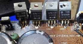
So I have this magnificently destroyed amp to deal with as you can see in the photos. I need help finding the rectifiers.
I did a search on the part number on the package and google turned up nothing.
Transformer became so hott some of the windings came out of the board. I have alot of work ahead of me.
I did a search on the part number on the package and google turned up nothing.
Transformer became so hott some of the windings came out of the board. I have alot of work ahead of me.
Attachments

I am attempting to learn more about these JL 1000's and improve my knowledge. These require a tad more experience then the generics and i want to know what makes them tick.
Most of my repairs are more for experience rather than profit. Repairing amplifiers is more of a hobby then a job. I am a fulltime rework technician in a factory so the electrical knowledge i fall behind in. I repair factory defects in PCBs. I don't do any troubleshooting at work.
I did find the rectifierd. Its a SF 1606GA not SFI606GA. My mistake.
All you need is 400v.
The 600v has a higher forward drop and will run hotter.
You need two positive and two negative. You only mentioned the negative so I don't know if you noticed that.
Before you do too much work, make sure that the driver transformers survived if the FETs failed.
The 600v has a higher forward drop and will run hotter.
You need two positive and two negative. You only mentioned the negative so I don't know if you noticed that.
Before you do too much work, make sure that the driver transformers survived if the FETs failed.
Hope your board is intact, mine needs significant repair! Thankfully the power transformer survived, somehow.
JL 1000/1 Board Hole
JL 1000/1 Board Hole
Oh wow yeah i saw that. Id take yours over mine. Id have fun repairing that one. I hate anything to do with rewinding toroids.
Really? Cause I'd love to rewind a torroid, it's a lot less involved than repairing this 4 layer PCB lol.
If you get a copy of IPC7721 it shows some pretty unique ways to take on that damage. Id cut thar square out and us a piece of pcb stock, etch it to match the traces, mill out a groove in the edge, slot them together and epoxy them in place.
I can never get the windings tight and snug like i want them. Especially if its a transformer. I just need practice on some junk i think.
I can never get the windings tight and snug like i want them. Especially if its a transformer. I just need practice on some junk i think.
You can't just wrap and pull. For all of the outside bends, bend them 90°against the core . For the center do the same but then pull the strand back up and feed it through the core. Pull down while working the strand back and forth in the core, you'll see that each time you do, it will conform better to the inner corner.
Wearing grippy gloves helps greatly.
Tech tips 8, item 19 for those who have the tutorial.
Wearing grippy gloves helps greatly.
Tech tips 8, item 19 for those who have the tutorial.
Time to practice! I cant believe i didn't think about gloves. I have a pair of Maxi flex gloves perfect for the task! Thanks for posting page numbers. It helps me go back to reference much quicker.
TT7, item 11 may help.
For some amps, if they have a lot of damage and you don't know if you will be able to repair them, you can use a single strand in place of the bundle of strands. You use the same layout and ratios but only the single strand. A single strand of 18 is enough for low power testing.
For some amps, if they have a lot of damage and you don't know if you will be able to repair them, you can use a single strand in place of the bundle of strands. You use the same layout and ratios but only the single strand. A single strand of 18 is enough for low power testing.
Quick question: Is there any feasible method to identify a transformer core that has no markings on it? The core material or even part number?
If the core is good, you can wrap it with a number of turns (10 is common) and measure the inductance. From that, you should be able to calculate its permeability which will give you a ballpark number. For example, there are several ferrite materials that are used in the 2000-3000 range, F, P, 77, 73 and 78. In recent years, some manufacturers have gone to using very high permeability cores (10,000) but I never used any of those.
I have no idea what JL uses.
I have no idea what JL uses.
@bl4ckw1d0w
That's the general idea anyway. I wanted to just cut out a big chunk that was square in shape and fit it in, but that won't be possible in this case due to other traces being woven into the board in spots adjacent to the burned area. The RC filters on the power transformer for example are very close to where the damage ends, but I'd rather only repair just the burnt part and not make more work for myself. I'll likely use a board 1/2 original thickness for the core, then single glass layers to build it back up to the point where I can glue the original surface foil back down. It's labor intensive, no doubt.
@Perry
With such a high mu core how do they keep from saturating? In old TV sets they used to gap the cores of the horizontal output transformers a tiny bit to avoid this when using ferrite, have you seen any gapped amplifier transformers?
The frequency, voltage and number of primary turns determine the maximum flux density. Those and the core are all used in calculations to make a transformer that won't saturate under the expected operating conditions. For the first list of cores I posted, a push-pull primary of about 4+4 at 25-30kHz is generally OK. For the higher permeability cores with large transformer cores, some use 3+3 so a high ratio and large windings will fit. Don't bet the farm on any of this. It's been almost 20 years since I did anything with cores other than wind them with what I know works.
- Home
- General Interest
- Car Audio
- JL 1000/1