I was given some very nice OPT's a while back, 3k4 Z pri, 8r Z sec, 50w lots of laminations, would do 100w easily. They have been wound to reduce inter winding C, 5 sections pri, 4 sections sec, so, brilliant LF and LF response. So far with a proto-typed LTP I've got a flat response from 100hz to 50khz with no NFB.
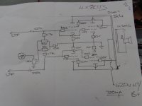
I've already built 120w monoblocks, so not looking for high OP, I've wound a mains toroid for 420v HT/B+ (though there are taps for 450v) @ 1A. I've wound the OP HTR's for series connection and have two 6.3v HTR windings as well as a -100v bias/CCS winding capable of 500mA if needed, which it won't be. For the knocked up prototype the HT psu is simple, big 450v 1100u cap, with RC filters/decoupling for PS & IP stages.
I could knock up a pretty simple class AB1 low THD amp (but where's the fun in that) but am wondering about maybe trying to make it 2nd H heavy going for a bit sound sculpturing, whether this will work or is a good idea have no idea as yet.
To make things hard I'm trying to use octal valves for the front end and PS, so can't use any beefy 12BH7/ECC99/12B4A/6S4A type B9 valves, stuck pretty much with Russian 6SN7/6H8C's though I did try triode strapped 6AC7's in a LTP which I have loads of, which worked well. The triode strapped curves for this valve are very linear, have also tried a 6H8C LTP. The first = less than 1% THD @ 20v RMS OP, but 3H is higher than 2H, but by only a few dB. The 6H8C LTP about the same, under 1% THD, 2H predominates. Both using CCS tail.
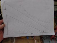
Drew a load line for the IP, bog standard common cathode stage, 50k Ra, 1k5 Rk, but gain is low, about 4X unbypassed, better obviously bypassed with a cap. Could use a triode strapped pentode here or parallel two triodes.
This is all off the cuff so far, just mucking about getting a feel for things. If you had the same OP stage, what would you do? Triode strap the 807's ( pointless as have UL taps on the OPT)?? Run in AB2? Direct couple PS and OP stage; would need another winding on the mains tfmr to get -300v ish, but could be done? Cascode LTP? Any ideas suggestions welcome.
Andy.
I've already built 120w monoblocks, so not looking for high OP, I've wound a mains toroid for 420v HT/B+ (though there are taps for 450v) @ 1A. I've wound the OP HTR's for series connection and have two 6.3v HTR windings as well as a -100v bias/CCS winding capable of 500mA if needed, which it won't be. For the knocked up prototype the HT psu is simple, big 450v 1100u cap, with RC filters/decoupling for PS & IP stages.
I could knock up a pretty simple class AB1 low THD amp (but where's the fun in that) but am wondering about maybe trying to make it 2nd H heavy going for a bit sound sculpturing, whether this will work or is a good idea have no idea as yet.
To make things hard I'm trying to use octal valves for the front end and PS, so can't use any beefy 12BH7/ECC99/12B4A/6S4A type B9 valves, stuck pretty much with Russian 6SN7/6H8C's though I did try triode strapped 6AC7's in a LTP which I have loads of, which worked well. The triode strapped curves for this valve are very linear, have also tried a 6H8C LTP. The first = less than 1% THD @ 20v RMS OP, but 3H is higher than 2H, but by only a few dB. The 6H8C LTP about the same, under 1% THD, 2H predominates. Both using CCS tail.
Drew a load line for the IP, bog standard common cathode stage, 50k Ra, 1k5 Rk, but gain is low, about 4X unbypassed, better obviously bypassed with a cap. Could use a triode strapped pentode here or parallel two triodes.
This is all off the cuff so far, just mucking about getting a feel for things. If you had the same OP stage, what would you do? Triode strap the 807's ( pointless as have UL taps on the OPT)?? Run in AB2? Direct couple PS and OP stage; would need another winding on the mains tfmr to get -300v ish, but could be done? Cascode LTP? Any ideas suggestions welcome.
Andy.
Attachments
Last edited:
You need magnetic headroom, if the setup incorporates a GNFB loop.
3400 Ω primary you say. That mates well with KT88s and 6550s. As a member of the 6L6 clan, the 807 works well with 6600 Ω primary "iron". PPP 807s would be OK in combination with a 3400 Ω primary.
3400 Ω primary you say. That mates well with KT88s and 6550s. As a member of the 6L6 clan, the 807 works well with 6600 Ω primary "iron". PPP 807s would be OK in combination with a 3400 Ω primary.
Yes, 3400r pri Z, I did the calcs and load line off the STC data for the 807. Also have some 6164's and a few TV valves but the quad of 807's are more or less matched, as you see from the schematic i can adjust bias and OP balance.
Andy.
Andy.
I also have some 807's and would like to find a suitable project for them. From what I have read so far, they have a limitation on screen voltage (250v, according to the data sheet), but sound better and better as plate voltage is increased (up to 600v). That would seem to rule out ultralinear for the best performance from them, unless I have misunderstood how a screen could have a much lower voltage when connected to a UL tap.
So I will be following this thread with interest!
So I will be following this thread with interest!
I am just building a similar project, with a single pair of 807's. I will publish the circuit diagram and first measurements after everything is set up (might take months).
Looking at your schematic in Post # 1, I think you need to add 2 more adjustable fixed bias circuits. Each tube should have its individual bias adjustments.
(unless you are willing to make the tradeoffs of using 4 individual self bias resistors, and 4 individual bypass caps). And that is what I would do, make the tradeoff, and have individual self bias.
Good 807 tube screens are rated for 300V in pentode mode, and 400V in triode wired mode.
In pentode mode, with the screen at 300V, and when the plate goes to 50V, the screen current goes very high.
In triode mode and 400V, as the plate goes to 50V, the screen is there too (no high screen current).
As the plate goes to 750V, the screen goes there too, but since the control grid is extremely negative (maybe 2X the quiescent bias), the screen current is almost at cutoff (no harm done).
I estimate that the screens will work OK at 350V in UL mode. With a 40% UL tap, as the plate goes to 50V (moves down 300V), the screen moves downward an amount of 120V (300 x 40%). That puts the screen at 230V, which is far less than the 300V of pentode mode.
How about that!
If you really want to use 420V B+, and UL mode, I suggest you at least look at a more modern Beam Power tubes that habe much higher screen voltage rating than the 807.
807 tubes are rugged, but if you get them to work reliably this way, let us know the manufacturers of the tubes, and if you listen to the amp at full power.
Do not get me wrong, I have designed amplifiers with 807 tubes, but I never put them in a design with 420V B+ combined with UL operation.
Some people have a 100 Watt amplifier, and then never listen to them at more than 10 to 30 Watts. That is fine, unless the amp is a guitar amp, and in a large venue.
Just my opinions.
Your mileage may vary.
Last edited:

I also have some 807's and would like to find a suitable project for them. From what I have read so far, they have a limitation on screen voltage (250v, according to the data sheet), but sound better and better as plate voltage is increased (up to 600v). That would seem to rule out ultralinear for the best performance from them, unless I have misunderstood how a screen could have a much lower voltage when connected to a UL tap.
So I will be following this thread with interest!
How to have your cake and eat it too, is always an issue. This time, if you spend enough, you can. Buy custom, separate, screen grid winding O/P "iron". You get the desired UL %, plus the distortion control benefit regulating g2 B+ provides. O/P transformers that contain: primary, secondary, and tertiary windings are costly, but you definitely realize better performance.
Eli Duttman,
Thanks for the reminder of the tertiary screen windings.
Then compare the cost of the specialized output transformers for 807 UL;
versus the higher cost of tubes that have screens that can do higher voltage UL . . . tubes that can use lower cost standard output transformers.
Thanks for the reminder of the tertiary screen windings.
Then compare the cost of the specialized output transformers for 807 UL;
versus the higher cost of tubes that have screens that can do higher voltage UL . . . tubes that can use lower cost standard output transformers.
I've looked into the G2 Vmax issue and have found several sources that mention running the screen grids at higher than spec with no probs. I've run the OP stage as wired in the schematic at 50w for 20 mins of so without issue, it will never see this sort of punishment in reality.
Re biasing each valve individualy, I've tried this in the past and found it an absolute nightmare to set. You adjust V1 , all good, on to V2, as soon as you start to adjust V2, V1's bias changes as does V3 + V4, it's like whack a mole.
Thanks all, I'll take your comments on board and maybe have a rethink.
Andy.
Diabolical Artificer,
I remember adjusting 2 fixed bias settings and the interaction that causes.
That was too much trouble.
That is why I use a combination of reasonably matched tubes, and self bias.
The currents all come very close. Most push pull amps I designed and built had less than 500uA difference in the plate currents . . . automatically (self bias).
The loss of P-K voltage across the tube (lost to run the self bias voltage) does reduce the maximum power.
But I am willing to loose a little power, and get a much simpler setup.
It also facilitates very easy tube rolling.
Last edited:
One suggestion is to have a zener parallelled with a cap in series between the UL tap
and the screen , with a screen stopper closest to the screen.
200Volt zener combination in a possibility.
and the screen , with a screen stopper closest to the screen.
200Volt zener combination in a possibility.
For your possible interest.
For Parallel output tubes then 1/2 the Raa of the output tranny.
\http://www.tubezone.net/pdf/807stc.pdf
Following coz I have a dozen Amperex NIB 807 looking for a project.
This restoration job I did may also be of interest if you want to go "old hat". Thanks to Tim who hosted the schematics. Points of interest are the stacked power supplies providing high B+ but 1/2 B+ to the 807 screens and interstage /phase splitter tranny
https://dalmura.com.au/static/ChurchChimes.pdf
Cheers
Ian
Last edited:
This may be of interest - Feeding 807 G2 - Disquisitions ........... (and questions) and this - Beam Tetrodes and the 807 see 3rd paragraph. And this - Google Groups & this - diytube.com • View topic - UL 807s
Running 807 g2 over datasheet Vmax has been discussed for years, I've run them at 400v on a few prototypes, however I try to make the dissipation is kept with limits, IE 3.5w.
To test this point I'll get some less than brilliant 807's and leave em running all day, but I'm sure they'll be fine, 807's have been abused for donkeys years in far higher running conditions in linear amps and can, AFAIK take the abuse.
However, as interesting as this subject is, anyone have experience running em in AB2, A2, direct coupled to the PS stage or other weird and wonderfull configurations, I'm after building something a bit different to usual AB1. Doing a lot of reading up at present, then will do more testing later this week.
Andy.
Last edited:
In the past the great David Manley sold the monoblock VTL 120 del luxe, double p-p of 807.
One of my friend got one pair that work for years
The tube ran at high voltage, around 600 vdc also for g2 without problem , just need a good selection of tubes.
The russian are out of job, the ATS25 and 5933 are fine.
I don't remeber if I have again the diagram
Walter
One of my friend got one pair that work for years
The tube ran at high voltage, around 600 vdc also for g2 without problem , just need a good selection of tubes.
The russian are out of job, the ATS25 and 5933 are fine.
I don't remeber if I have again the diagram
Walter
Running 807 g2 over datasheet Vmax has been discussed for years, I've run them at 400v on a few prototypes, however I try to make the dissipation is kept with limits, IE 3.5w.
Staying within the published dissipation limits is the key to successfully taking some liberty with max. voltage limits. Mere volts, within reason, very rarely are a problem. OTOH, heat is the mortal enemy of all things electronic.
At least the major g1 resistor in post # 1, is 47k. It then goes through (1/2 of?) a 5k pot to a 10k to ground (60k total to ground with the pot centered.
The max spec for g1 resistor in fixed bias is 100k, and there are two g1's in parallel (two 807s). Post # 1 is a little beyond the 100k limit.
Just try and use a Lot more than 100k per g1, and then use a 600V screen without a fairly large dropping resistor, and wonder how long it will hold up.
Not in my house, unless it has a firesafe enclosure all around.
Last edited:
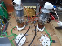
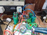
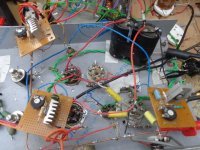
Now have these running in AB2 and am a lot happier with the result. I knocked up an AB1 amp, it worked ok, good specs, but was very unstable with HF oscillation, fixed that and it went into LF osc/motorboating. so, redid PSU, got rid of a lot of wiring, that fixed that issue. Tried a music test, didn't make me grin like an idiot.
Ripped out all the front end, took two 807's out, built a LTP with CCS + paralleled 6H8C's running at 12mA from a CCS, am now getting the same power out but with two less valves, stability is very good and a music test had me grandad skanking about the living room.
807 screen grids are run from a regulated 300v PSU, control grids at -25v, no grid leak or stoppers, no coupling cap, obviously. I love the sound of this AB2.
Early days yet, lots to tweak, have had issues with a front end going into oscillation, was using an ECC81 which I've found are bipolar and oscillate at the drop of a hat.
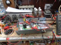
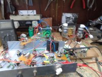
Some pics, Andy.
Ripped out all the front end, took two 807's out, built a LTP with CCS + paralleled 6H8C's running at 12mA from a CCS, am now getting the same power out but with two less valves, stability is very good and a music test had me grandad skanking about the living room.
807 screen grids are run from a regulated 300v PSU, control grids at -25v, no grid leak or stoppers, no coupling cap, obviously. I love the sound of this AB2.
Early days yet, lots to tweak, have had issues with a front end going into oscillation, was using an ECC81 which I've found are bipolar and oscillate at the drop of a hat.
Some pics, Andy.
Attachments
Yep, saw that Chris, thanks, it's not in AB2 and don't like the common cathode resistor but it is a good source for ideas.
Andy.
Andy.
The journey continues... I've been mucking about with this too long really, had it running really well in AB2 especially after building a 300v regulated PSU for the screen grids, then whilst "testing" things started going bang. blew a diode, MJE340 in a CCS and yesterday killed an 807 whilst running the thing in AB2 UL.
I had this mad idea to see how it performed with the screen grids connected to the UL taps instead of the regulated 300v. At first, surprisingly well. Then after someone thought how much can I get out of this thing an 807 arced over inside and started going blue/purple inside, whoops.
Well, it's bleeding obvious, the datasheet says class AB2 g2 300v, 23mA/200mW max, g2 400v god knows how many mA = sad 807. I then hit on the idea of putting a big 10k on g2 to keep g2 max within specs, which worked ish, but not ideal.
So, I'm abandoning that idea, but will store in the old noggin for later re-apprissal, this might work with valves with a higher Vg2 like the 6L6GC/EL34/KT88, though I dare some of you will say it's a completely daft idea.
I've now re-jigged the OP stage, back to four valves but this time I'm having a play with extended class A where two valves are configuered as triodes, two as beam tets, the idea being the amp runs in class A for normal listening then the beam tet PP stage kicks in if more power OP is needed. Anyone tried this out?
Although the amp sounded really nice in AB2, the OPT's were wound with a PPP OP stage in mind, and a friend in Oz is after sending me some NOS 807's bless im, therefore i'm leaning towards either class AB1 or extended class A. The OPT for class AB2 would really need a bigger pri Z, this after trying a bigger secondary load, power OP went up and there was less distortion.
So, I need to stop bogging about, decide on the OP stage and get the chassis top plate fettled, get the bu*ger built. One other consideration helps me to decide to abandon class AB2 for now is the PSU. I've already rewound the mains tfmr a few times, for AB2 a hefty negative rail is needed, more than the present winding is capable of. Could use another tfmr but weight is an issue, it's already going to be heavy as is.
Thoughts welcome, Andy.
- Home
- Amplifiers
- Tubes / Valves
- 807 PPP UL amp, ideas?