Apologies if this has been covered, did not find it in search.
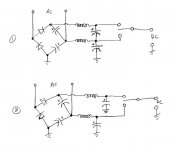
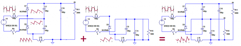
What is the proper way to add LC filtering to a voltage doubler? I have attached a sketch to show what I mean.
For the case where EITHER the Vdc or 2Vdc legs of the doubler will be used (shown as switch selectable), is (1) or (2) the correct method? Or is there another preferred option?
For the case where BOTH the Vdc and 2Vdc legs will be used (current draw simultaneous), is (1) or (2) the correct method? Or is there another preferred option?
TIA
Attachments
Not sure there is a 'correct' method. As usual, there are tradeoffs.
Example #1 has the non-trivial advantage of a much less expensive capacitor for the 2Vdc filter, at the expense of somewhat higher ripple in the 1Vdc output -- but only as the current demand on 2Vdc increases.
It also offers more gracious and consistently/reliably timed power up/power down sequences.
Those chokes are gonna be kinda expensive, too. Are you sure they're warranted? It isn't like a choke input for a valve rectifier -- you already have the doubler capacitors doing a lot of smoothing.
Regards
Here are the situations compared, for half-realistic conditions.
Note that I didn't care too much about the fairness of the comparisons: ideally, one would need to think about the total charge (C*V product) and/or total energy stored in the capacitors, and the same with the inductors.
Here, both the high and low outputs are simultaneously loaded.
First, the low voltage outputs:
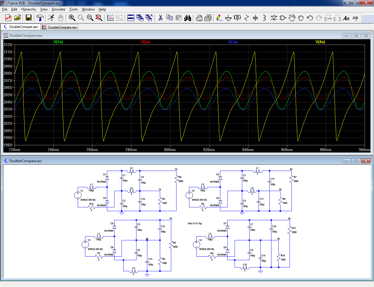
The best solution depends on the priority: highest voltage or lowest ripple, but #2 looks like a good tradeoff.
The HV outputs:
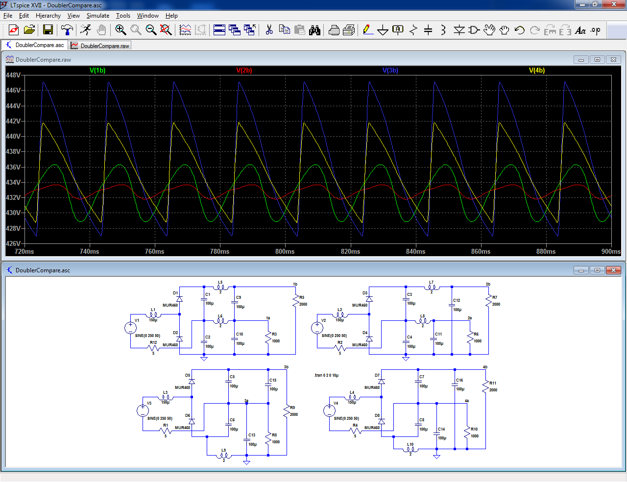
Again, #2 looks like the best tradeoff.
One would need to also compare the situations with single outputs loaded.
#2 looks good, but it requires 2x the number of chokes compared to Ketje's solutions: having a single, significantly larger choke would probably be advantageous in many cases
I include the .asc, if someone wants to investigate further:
Note that I didn't care too much about the fairness of the comparisons: ideally, one would need to think about the total charge (C*V product) and/or total energy stored in the capacitors, and the same with the inductors.
Here, both the high and low outputs are simultaneously loaded.
First, the low voltage outputs:
The best solution depends on the priority: highest voltage or lowest ripple, but #2 looks like a good tradeoff.
The HV outputs:
Again, #2 looks like the best tradeoff.
One would need to also compare the situations with single outputs loaded.
#2 looks good, but it requires 2x the number of chokes compared to Ketje's solutions: having a single, significantly larger choke would probably be advantageous in many cases
I include the .asc, if someone wants to investigate further:
Attachments
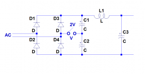
The one choke solution looked not bad, a C-L-C for the two outputs.
But the result isn't that good.The line frequency rippel of the half voltage and double frequenty of the doubler add-up resulting in a double amplitude line frequency rippel 🙁
Perhaps the circuit is intended for a tetrode PP output where the screen grids needs half the voltage of the anode.In that case the current in the low voltage part is much smaller resulting in a mostly double frequency rippel.
With a choke of say 10H, often used in tube amps, the circuit could be of use.
Mona
Attachments
- Home
- Amplifiers
- Power Supplies
- Adding LC filter to voltage doubler?