Hi everyone, I'm new here and need some help repairing my P2100 amp.
Random noise (attached) appeared only on one channel. Its level is constant and does not depend on volume pot position, but I noticed, that after switching off (breaking the mains) and while the sound path is still "on" for 5-6 seconds until the total shutdown - there is no noise and audio signal is clear as it should be. First guess was - one of the diode pairs DC10-1/DC10-1R, so replaced them both to 1N4007s paired accordingly, but nothing changed...
...any ideas? Appreciate any help
Thanks a lot!
Attachments
Looks like something no longer copes with full operating voltages. My prime candidates would be everything with a substantial amount of voltage relative to rated, predominantly:
* electrolytics (e.g. 220µ/63, 470µ/16 x2)
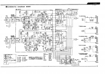
* transistors like VAS cascode TR9, output stage e.g. TR14, TR15, maybe input stage transistors TR1/2 or cascode TR3/TR4 (though those are 120 V types @ 30 V)
* high value carbon film resistors are also worth checking especially if looking toasty
Has the unit been recapped yet? It's no longer a spring chicken at this point, and while the big cans may still be good if their life wasn't too hard (an ESR meter would make that clear), I wouldn't trust some of the small electrolytics much. I would generally go for same capacitance and choose voltage rating for same physical size unless that gets silly high (typically >100 V). Good quality parts (e.g. Panasonic FC) from reputable distributors.
Notable exceptions from the general rule:
* 100µ/10V input series caps (between the 220ks): Oversized C, probably dead at this point due to lack of appreciable DC bias. Don't see why 10µ (50-63 V) wouldn't do, possibly a low leakage series, or a DIY bipolar (2x 22µ back-to-back, 35-50 V maybe?) if not too unwieldy
* 470µ/10V input bootstrap/feedback - again, likely dead. Would suggest a DIY bipolar with 470µs if feasible, low cutoff would still be plenty low enough.
* You may have difficulty even finding a 0.47 µF electrolytic, in which case try substituting a 470 nF film cap (no particular voltage rating needed) - a type with longer leads (e.g. Panasonic) would fit better than e.g. the WIMAs with their short stubby legs.
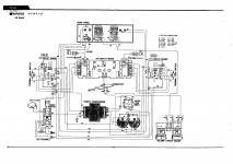
A schematic that's not tiny and/or blurry for once is appreciated btw.
* electrolytics (e.g. 220µ/63, 470µ/16 x2)
* transistors like VAS cascode TR9, output stage e.g. TR14, TR15, maybe input stage transistors TR1/2 or cascode TR3/TR4 (though those are 120 V types @ 30 V)
* high value carbon film resistors are also worth checking especially if looking toasty
Has the unit been recapped yet? It's no longer a spring chicken at this point, and while the big cans may still be good if their life wasn't too hard (an ESR meter would make that clear), I wouldn't trust some of the small electrolytics much. I would generally go for same capacitance and choose voltage rating for same physical size unless that gets silly high (typically >100 V). Good quality parts (e.g. Panasonic FC) from reputable distributors.
Notable exceptions from the general rule:
* 100µ/10V input series caps (between the 220ks): Oversized C, probably dead at this point due to lack of appreciable DC bias. Don't see why 10µ (50-63 V) wouldn't do, possibly a low leakage series, or a DIY bipolar (2x 22µ back-to-back, 35-50 V maybe?) if not too unwieldy
* 470µ/10V input bootstrap/feedback - again, likely dead. Would suggest a DIY bipolar with 470µs if feasible, low cutoff would still be plenty low enough.
* You may have difficulty even finding a 0.47 µF electrolytic, in which case try substituting a 470 nF film cap (no particular voltage rating needed) - a type with longer leads (e.g. Panasonic) would fit better than e.g. the WIMAs with their short stubby legs.
A schematic that's not tiny and/or blurry for once is appreciated btw.
Thanks for such detailed answer!
Needed second opinion to decide on recapping, as all caps look good, but it seems like no one touched them since '77. Will start from that. I have a bunch on 22uf/25v bipolar Nichicon Muse, so will put them on inputs instead of 100uf/10v.
Also noticed that on the other channel, which is ok, TR1 and TR2 (2SA872A) are changed to 2SA1145, which are much cheaper than new old stock 2SA872A. However, I'm thinking of buying 2 of original Hitachi and change them back. Is it worth doing? Or 2SA1145 is a good replacement? I looked at their datasheets and there are slight differences, but have no experience with them.
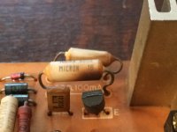
Attached a photo of resistors that are indeed toasty. Are metallic film ok for exchange?
Thanks again for your help
Needed second opinion to decide on recapping, as all caps look good, but it seems like no one touched them since '77. Will start from that. I have a bunch on 22uf/25v bipolar Nichicon Muse, so will put them on inputs instead of 100uf/10v.
Also noticed that on the other channel, which is ok, TR1 and TR2 (2SA872A) are changed to 2SA1145, which are much cheaper than new old stock 2SA872A. However, I'm thinking of buying 2 of original Hitachi and change them back. Is it worth doing? Or 2SA1145 is a good replacement? I looked at their datasheets and there are slight differences, but have no experience with them.
Attached a photo of resistors that are indeed toasty. Are metallic film ok for exchange?
Thanks again for your help
Attachments
Input is bootstrapped, so the lower capvalue is ok....I have a bunch on 22uf/25v bipolar ... instead of 100uf/10v.
Most important: Vce, Ic and Pd should come close on specs....TR1 and TR2 (2SA872A) are changed to 2SA1145...there are slight differences...
Send pm with datasheets if needed.
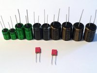
Ready for recapping. Sizes match except axial, values almost match too:
1x 100/10 -> 100/20 bipolar Nichicon Muse
1x 470/10 -> I have only 330/25 bipolars, will it be ok?
2x 470/16 -> 470/25 Nichicon Muse
1x 220/63 -> 220/100 Elite low esr, not axial, but anyway
1x 0.47/35 -> 470n/63 Wima w/ 5mm contact pitch, will fit well
Is there any reason of using axial caps from electrical point of view?
Attachments
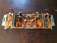
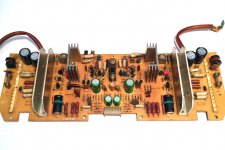
Recapping is done
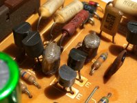
Can anyone suggest what to do with resistors and caps on the pictures - which type is that and which replacement is the best?
Will try the board now
Thanks a lot for your help.
Can anyone suggest what to do with resistors and caps on the pictures - which type is that and which replacement is the best?
Will try the board now
Thanks a lot for your help.
Attachments

That's 30% less capacity... not really shocking....1x 470/10 -> I have only 330/25 bipolars, will it be ok?
None.Is there any reason of using axial caps from electrical point of view?
Capacitors degrade swifter when close to heat sources like heat sinks (!). Those large caps are not happy neighboring these sinks. Use tropical spec caps (105ºC) there preferably....what to do with resistors and caps on the pictures ...
Two very nice rolled styroflex capacitors... almost the best one can get. I prefer those above all other. Soundless.
That 68ΩK resistor is near TR8, the other the 470Ω near TR9 I guess. Only to be replaced with exact values, but the power spec is not shown. Leave it if all works fine.
Thanks for pointing to styroflex!
Just tried the amp and noise is still there, but much quieter now. Shutdown time increased from 5 seconds on old caps to about 12 seconds now (slow fade out of power LED). So it seems that old caps were drained anyway.
Now I guess its time to check transistors as sgrossklass suggested.
Just tried the amp and noise is still there, but much quieter now. Shutdown time increased from 5 seconds on old caps to about 12 seconds now (slow fade out of power LED). So it seems that old caps were drained anyway.
Now I guess its time to check transistors as sgrossklass suggested.
Try to find the hotspot with a 1µF/100V nonpol cap, one side to ground and prick (the other side, duh) into the circuit at various points to find out if that odd noise can be cancelled. Shorting the source, so to say.
Thanks for the tip. Made a probe with a big 1uF/630 film cap, but can't figure out which points should I try. I also have a multimeter, old analog scope and a chinese transistor tester.Try to find the hotspot with a 1µF/100V nonpol cap ... at various points
Things tried so far after recapping:
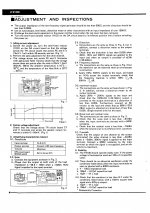
1) Measured idling voltage as described in "Adjustments and inspections" section of the manual (attached):
Turning 1k pot to leftmost position on both channels gives strange results: after power up, idling voltage if noisy channel fluctuates as it should and then stabilizes to about 22mV in 3-4 minutes (in leftmost position, so I cannot even set 13mV as described in the manual), but when the noise spikes happen - it sags to 8-10mV for a moment (what the meter reads) and then stabilizes again.
When, a single loud click can happen and it sags even more and then there is no noise for like 30 seconds and then it starts again...

However, a healthy channel gives 44mV idling voltage immediately after powering up and stays like that... too much, so looks like it is also not so healthy..
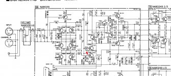
2) Probed the input to DA board with a scope - no noise visible. Then tried TR8's base (attached, red arrow) and the noise is visible with about 400mVp-p. Does that mean that the problem is in the left part of the schematic TR1-TR7? 😕
What should I do next? I'm even thinking to desolder and check every component, it already doesn't look so scary after all these explorations.
PS: Sorry for such long and confusing text.
Thanks!
Attachments
- Home
- Amplifiers
- Solid State
- Yamaha P2100 - Noise on one channel