Hello everyone, I'm new in this forum!
I'm the proud owner of a Krell KSA 100 EUR amplifier. It works fine, but it has never been recapped, and I'm using it a lot. So I thought it is time to do some maintenance work.
Here's what I plan to do:
Anything else you would recommend doing, while in there?
I do have schematics for my amp, and before I take anything apart, I'd like to understand the schematics. I started with the protection circuit (the board at the rear end of the amplifier).
I do have a couple of questions about this:
These are just my initial questions 😀 and I guess there will be many more... 😎 so please be patient with me...
I'm the proud owner of a Krell KSA 100 EUR amplifier. It works fine, but it has never been recapped, and I'm using it a lot. So I thought it is time to do some maintenance work.
Here's what I plan to do:
- Replace all capacitors
- Replace all potentiometers
- I am considering applying new thermal paste and insulators on all the transistors. But I'm not sure if I should do that, if I'm not also replacing the parts. The stress on the PCB and on the components might outweigh the potential benefits.... Thoughts?
- Clean all connectors
- Adjust DC offset, idle current, ...
Anything else you would recommend doing, while in there?
I do have schematics for my amp, and before I take anything apart, I'd like to understand the schematics. I started with the protection circuit (the board at the rear end of the amplifier).
I do have a couple of questions about this:
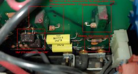
- The schematics shows some weird resistor arrays with switches, which I can't identify on the board. Instead of the 1k resistor and the resistor array, I see on the board a 100ohms resistor and a 12.4ohms resistor + a 100ohms potentiometer. From my understanding, this circuit shuts down the amp, if too much current flows through the 1ohm resistor in the output path. So my question is: How do I calibrate this circuit?
- For C32 and C33 the schematics gives a value of "100" but on the board it looks like its a 10pF capacitor. What is the correct value of this capacitor?
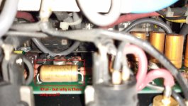
- The schematics shows two 47uF capacitors (C28, C29) - one for each channel. But on the board I see only one 47uF capacitor!! What's wrong here?
- Obviously the schematics I have does not exactly match my model (maybe a slightly older or newer revision). Does anyone have the schematics for my exact model?
These are just my initial questions 😀 and I guess there will be many more... 😎 so please be patient with me...
Attachments

Rather than replace the thermal paste, just retorque the mounting hardware.
I'll bet there actually are two 47uF caps (somewhere) on the board.
Might want to replace those output relays.
I'll bet there actually are two 47uF caps (somewhere) on the board.
Might want to replace those output relays.
Last edited:
Hi rayma, thanks for your response.
Retorquing the mounting hardware is a good idea. Will do that.
It is difficult to take a picture of the entire board now (I haven't started disassembling the amp yet), but with my eyes I can see every part of the board and I'm sure there is only one of these 47uF caps on the board... It doesn't make sense to me, but that's what I see...