Hello everyone.
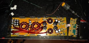
I have this class D full range amplifier (in my country it is marketed under various brands, diaboliko, ipnosis etc).
Unfortunately the amplifier presents problems on only one of the two channels.
One works perfectly, the other shortens the entire amplifier.
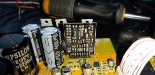
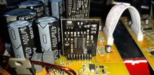
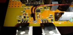
The 8-pin integrated near the output mosfets is an irs2011 and is driven by the "FDM04-RC" driver board of which I have found nothing on the internet.
By doing some tests, I found the linear regulator to be short with the relative zener diode, which I promptly replaced.
I also replaced the open gate resistors and also the irs2011.
Unfortunately when I install the new IRS2011 (without output mosfet) the amplifier goes into protection.
If I remove IRS2011 and control at input pins 5 and 6, there is nothing (no waveform injecting signal into the amplifier) while on the working channel, on pins 5 and 6 of IRS2011 there are two beautiful square waves.
Does anyone know FDM04-RC?
All ICs on this driver board are deleted.
If someone knows a scheme or at least the component codes, I could try to understand what happens.
I have this class D full range amplifier (in my country it is marketed under various brands, diaboliko, ipnosis etc).
Unfortunately the amplifier presents problems on only one of the two channels.
One works perfectly, the other shortens the entire amplifier.
The 8-pin integrated near the output mosfets is an irs2011 and is driven by the "FDM04-RC" driver board of which I have found nothing on the internet.
By doing some tests, I found the linear regulator to be short with the relative zener diode, which I promptly replaced.
I also replaced the open gate resistors and also the irs2011.
Unfortunately when I install the new IRS2011 (without output mosfet) the amplifier goes into protection.
If I remove IRS2011 and control at input pins 5 and 6, there is nothing (no waveform injecting signal into the amplifier) while on the working channel, on pins 5 and 6 of IRS2011 there are two beautiful square waves.
Does anyone know FDM04-RC?
All ICs on this driver board are deleted.
If someone knows a scheme or at least the component codes, I could try to understand what happens.
Attachments
Last edited:
What is the DC voltage on pins 6, 7, 11 and 14 of the 14 pin IC on the driver board?
You may be losing the drive because you're opening the feedback loop.
You may be losing the drive because you're opening the feedback loop.