Hello,
I have heard a lot about the STC/ITT 5A/152M being one of the best sounding driver tubes in triode mode.
Has anybody a diagram (Ua/Ia) for triode mode connection or better a SPICE model?
I want to use it driving a AD1.
Thanks
I have heard a lot about the STC/ITT 5A/152M being one of the best sounding driver tubes in triode mode.
Has anybody a diagram (Ua/Ia) for triode mode connection or better a SPICE model?
I want to use it driving a AD1.
Thanks
Hello, I remember there is a schematic published in Glass Audio, using this valve as a driver in a single ended 300B amp. I will search for the nr/year in my magazines and return about this. Have you found any application data since you posted the question? Rgds, adam2a3
Hi guys, just reviving this thread in case anyone has any information of any kind on the 5A/152. Any tube that drives a 300b well is interesting. All replies welcome!
They are available in quantity from Billingtons, if that is helpful.
Tube data: 5A-152M.pdf
Similar properties to a C3G, since it is designed to try and push a signal down a long length of wire.
Another tube like that is the 6CH6/EL821: 6CH6 Valve Museum
gm is similar for that tube, so it would be interesting if 6CH6 could be a good driver tube. (It does make a good triode because S3 is taken to a pin).
Last edited:
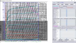
I build this model based on the screen current max 5mA and IV plate curve where the bottom curve is -4V, and derived a Mu of about 40 for triode mode.
Code:
**** 5A_152M ******************************************
* Created on 10/14/2020 19:02 using paint_kip.jar
* [URL="http://www.dmitrynizh.com/tubeparams_image.htm"]www.dmitrynizh.com/tubeparams_image.htm[/URL]
* Plate Curves image file: 5a-152m.png
* Data source link: <plate curves URL>
*----------------------------------------------------------------------------------
.SUBCKT 5A_152M P G2 G K ; LTSpice tetrode.asy pinout
* .SUBCKT 5A_152M P G K G2 ; Koren Pentode Pspice pinout
+ PARAMS: MU=40.7 KG1=732.6 KP=459.13 KVB=12.36 VCT=0.216 EX=1.273 KG2=911.06 KNEE=62.5 KVC=2.035
+ KLAM=1.367E-11 KLAMG=3.498E-4  KD=0.2464 KC=0.2604 KR1=5.72E-4 KR2=0.0672 KVBG=0.00285 KB1=2 KB2=1.26 KB3=1.78 KB4=27.52 KVBGI=0.03904 KNK=-0.044 KNG=0.006 KNPL=50 KNSL=11 KNPR=120 KNSR=29
+ CCG=10P CGP=0.018P CCP=5P VGOFF=-0.6 IGA=0.001 IGB=0.321 IGC=8 IGEX=1.64
* Vp_MAX=300 Ip_MAX=25 Vg_step=0.5 Vg_start=-0.5 Vg_count=15
* X_MIN=83 Y_MIN=15 X_SIZE=561 Y_SIZE=625 FSZ_X=1296 FSZ_Y=736 XYGrid=true
* Rp=1400 Vg_ac=20 P_max=5 Vg_qui=-4 Vp_qui=300
* showLoadLine=n showIp=y isDHP=n isPP=n isAsymPP=n isUL=n showDissipLimit=y
* showIg1=y isInputSnapped=y addLocalNFB=n
* XYProjections=n harmonicPlot=y dissipPlot=n
* UL=0.43 EG2=150 gridLevel2=y addKink=y isTanhKnee=n advSigmoid=y
*----------------------------------------------------------------------------------
RE1  7 0  1G    ; DUMMY SO NODE 7 HAS 2 CONNECTIONS
E1   7 0  VALUE=  ; E1 BREAKS UP LONG EQUATION FOR G1.
+{V(G2,K)/KP*LOG(1+EXP((1/MU+(VCT+V(G,K))/SQRT(KVB+V(G2,K)*V(G2,K)))*KP))}
RE2  6 0  1G    ; DUMMY SO NODE 6 HAS 2 CONNECTIONS
E2  6 0  VALUE={(PWR(V(7),EX)+PWRS(V(7),EX))} ; Kg1 times KIT current
E4   8 0  VALUE={V(P,K)/KNEE/(KVBGI+V(6)*KVBG)}
E5  81 0  VALUE={PWR(V(8),KB1)}
E6  82 0  VALUE={PWR(V(8),KB2)}
E7  83 0  VALUE={PWR(V(8),KB3)}
E8   9 0  VALUE={PWR(1-EXP(-V(81)*(KC+KR1*V(82))/(KD+KR2*V(83))),KB4)*1.5708}
RE4  8 0  1
RE5 81 0  1
RE6 82 0  1
RE7 83 0  1
RE8  9 0  1
RE21 21 0 1
E21  21 0 VALUE={V(6)/KG1*V(9)} ; Ip with knee but no slope and no kink
RE22 22 0 1 ; E22: kink curr deviation for plate
E22  22 0 VALUE={V(21)*LIMIT(KNK-V(G,K)*KNG,0,0.3)*(-ATAN((V(P,K)-KNPL)/KNSL)+ATAN((V(P,K)-KNPR)/KNSR))}
G1   P K  VALUE={V(21)*(1+KLAMG*V(P,K))+KLAM*V(P,K) + V(22)}
G2   G2 K  VALUE={V(6)/KG2*(KVC-V(9))/(1+KLAMG*V(P,K)) - V(22)}
RCP  P K  1G     ; FOR CONVERGENCE
C1   K G  {CCG}  ; CATHODE-GRID 1
C2   G P  {CGP}  ; GRID 1-PLATE
C3   K P  {CCP}  ; CATHODE-PLATE
RE23 G 0 1G
GG G K VALUE={(IGA+IGB/(IGC+V(P,K)))*(MU/KG1)*
+(PWR(V(G,K)-VGOFF,IGEX)+PWRS(V(G,K)-VGOFF,IGEX))}
.ENDS
*$
Attachments
Yes - it seems there are quantities around and much cheaper than C3G. Thanks for the information.
- Home
- Amplifiers
- Tubes / Valves
- 5A/152M perfect driver? SPICE?