I need some help. I bought two of these boards a couple of years and have been using them as stereo power amps. I have previously bridged 2 SS amps using boards obtained after an article in the magazine Everyday Practical Electronics, now EPE.
To power the module (LM833 based) you need a split rail supply and it is suggested that you piggy back the amps own supply. This has been fine in the working pair.
I have hacked into the supply of one of L12 boards and perhaps unwisely piggy backed the bridge rectifier and not the caps attached to it. All was well when using the light bulb limiter and so I gave it full power. It played for 20s and then started to die and a very small amount of the magic smoke appeared from the area near the +leg of the rectifier. I removed the rectifier and inserted another, but it would not fire up (bulb full brightness and no LED lit on amp board. The only other component in the area of "the smoke" is a 1uf tantalum bead cap which looked fine. I removed it and tested it and it is within spec. All other components look fine. Anyone have any ideas?
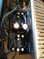
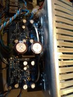
Not a lot to show. The + was attached to the + leg, the - to the - leg and the centre tap to the appropriate connection on the board. The bridged board would be drawing very small current to power the LM833 and I was surprised that something went wrong.
These pics are of the good board. The smoked one is identical
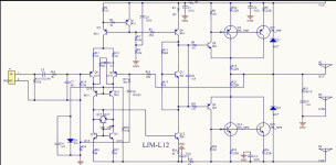
C28 was the cap I suspected smoked, but this checks out ok. The resistor to the right seems ok too (47k) and no signs of burning. I can't seem to find C28 on the schematic posted, nor the 47k resistor.


These pics are of the good board. The smoked one is identical
C28 was the cap I suspected smoked, but this checks out ok. The resistor to the right seems ok too (47k) and no signs of burning. I can't seem to find C28 on the schematic posted, nor the 47k resistor.


Last edited:
LM833 supply absolute max +/-18V (normally runs at +/-15V). What exactly is this module and can it handle the power amp supply voltage (what is the supply voltage for the L12's anyway?)
Below is a link to an article relating to the original use for the board as Unbal/Balanced module. EE then published an article showing that half of the board could be used as a bridging module.
https://www.eeweb.com/extreme-circuits/balanced-unbalanced-converter-for-audio-work
Taken from the EPE Bridge adaptor article (Oct 2010 - I have the magazine)
"We show it as using one LM833, IC1 and IC2 are deleted. The input signal is fed to op-amp IC3a which is connected as a unity gain buffer (output pin1 is connected to inverting input Pin2). The output of IC3a is fed via a 22uf NP cap and a 150ohm resistor to become the in-phase output signal. IC3a also drives IC3b which is connected as an inverting amplifier with a gain of -1 due to the 10k resistor connected to pins 6&7. IC3b's output is fed via a 22uf NP cap and a 150ohm resistor to become the out of phase output signal.
The power supply is taken from the existing amplifier (split rail) These supply rails are fed in via series resistors (R1-R4) and regulated using 15v1W Zener diodes which are shunted by 470uf caps. The table at (Fig2) shows the resistor values for various supply combinations to provide +/-15v supply rails.
As I said in the original post I have successfully used the same modules in another 2 amps without any problems.
C28 was the cap I suspected smoked, but this checks out ok. The resistor to the right seems ok too (47k) and no signs of burning. I can't seem to find C28 on the schematic posted, nor the 47k resistor.
Perhaps your board is the stereo MOSFET L12 board (w/built in power filter) from LJM while the posted schematic is the unrelated mono L12-2 (Bipolar) from LJM? Two different and unrelated designs?
I have not found a schematic for the MOSFET L12 board. I wondered if it was related to the L7 but then I noticed it does not have the same drivers for the output MOSFETs that the L7 has.
Replaced C28 tantalum today, still no joy. Strange nothing else looks dead.
Isn't that a monolithic (ceramic) capacitor not tantalum? What value did you replace it with?
I suggest you probe all of the transistors and resistors and look for shorted transistors and higher than expected resistor values.
- Home
- Amplifiers
- Solid State
- LJM L12 Stereo amp board
