Main characteristics:
- triode connected PP-output stage driven by OP-amp. (NE5532)
- max. output power 20 W with 5k OPT and 18 W with 6.6k OPT
- video output pentodes (6P15P) used because those require low bias- and drive voltage
- fixed bias arranged by means of constant voltage sources at the cathodes to make current drive (AB2) possible
Attachments
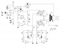

At maximum power the peak grid-cathode voltage goes to about 6 volts positive. The cathode bias is some 10 to 11 volts, so peak grid to ground voltage 16 to 17 volts.
One more feature; output impedance with 6k6 OPT and 12 dB GNFB is 0.8 ohms.
One more feature; output impedance with 6k6 OPT and 12 dB GNFB is 0.8 ohms.
Last edited:
NE5532 with max. allowed supply voltage (+/-22 Vdc) can drive up to some 20 V peak to positive direction. I chose 6P15P because it has (in triode mode) higher gain and lower bias voltage than other types, such as EL84. EL84 needs some 14...15 V bias, but 6P15P only 10 to 11 V with the same standing current (30 mA).
With EL84 the max. power would be some 15 W while with 6P15P it is 20 W.
I am aware of the fragility of the screen of 6P15P. Therefore I used triode connection. At idle, the total Ik = 30 mA and the g2-current is 4 mA.
So far I am testing and will measure the screen dissipation too.
With EL84 the max. power would be some 15 W while with 6P15P it is 20 W.
I am aware of the fragility of the screen of 6P15P. Therefore I used triode connection. At idle, the total Ik = 30 mA and the g2-current is 4 mA.
So far I am testing and will measure the screen dissipation too.
Last edited:
...have you also simulated this circuit?
Only the output stage, not the whole amplifier.
This is my second construction with OP-amp driver and CVS bias, which I have simulated as a complete amplifier. Therefore I did not need more simulations with 6P15P.
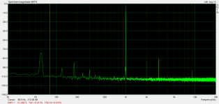
Attached is the distortion spectrum I got.
Is that the spectrum of the driver only ? What level and gain (NFB) ?
You need pull up resistors on the emitters to maintain low impedance at cut off transition . Using BD140 5v/100ma without heat sink I get 0.22 ohms .
At "cut off" the cathode current does not drop to zero. There is some 1.5 mA at the most negative drive voltage.
I have monitored the cathode voltage with an oscilloscope and there is only minor ripple during the whole drive cycle.
I have monitored the cathode voltage with an oscilloscope and there is only minor ripple during the whole drive cycle.
Pardon me if this comment is like a fâhrt in a flower show, but what is the point of using a high-gain op-amp (100× / +40 dB, before GNFB) to completely 'tame' the output valve transfer curves to the point of being flat-line linear?
Its not like low-cost modestly powerful TV pentodes are inherently awesome amplification devices that have no other peer in the linearity department!
After all, one still has to obtain a big, heavy (and often more expensive than the valves…) output transformer; and one has to work with fairly high voltages; and one needs to 'deal' with valves that don't age in lockstep very gracefully, typically.
The point of using valves (at least to me, a frequent reader of the TUBES forum) is at least nominally to serendipitously benefit from the whole chain-of-valves non-linearities to acoustically enrich the signal, and to not (normally) have a very high output damping factor, allowing the speaker cones and crossovers to similarly exert their modest resonances on the playback source.
Because if one is going to lash the output into tight linearity, erasing the pentode signature using fairly aggressive GNFB, well … (this may be the fâhrt), then why use pentodes-and-transformers at all? A conventional complimentary BJT or MOSFET output stage … with similar GNFB, delivers high DF (30+), high current sourcing for program transients, modest working voltages, and at least nominally the opportunity to have all-circuit-path devices that largely DON'T age quixotically.
OK, OK, OK. I'll go back to my cave. The answer is probably obvious:
…Because its a cool circuit, Goat…
Fair enough. I'm tired, its 4 AM in Californian, and I'm facing the prospect of yet another morning without coffee. Carry on. Where did I misplace my flint-and-steel? Harrumph. GoatGuy ✓NE5532 with max. allowed supply voltage (+/-22 Vdc) can drive up to some 20 V peak to positive direction. I chose 6P15P because it has (in triode mode) higher gain and lower bias voltage than other types, such as EL84. EL84 needs some 14...15 V bias, but 6P15P only 10 to 11 V with the same standing current (30 mA).
With EL84 the max. power would be some 15 W while with 6P15P it is 20 W.
I am aware of the fragility of the screen of 6P15P. Therefore I used triode connection. At idle, the total Ik = 30 mA and the g2-current is 4 mA.
So far I am testing and will measure the screen dissipation too.
So it is possible to get 15w out of an el84 triode strapped pair in class AB2?
Any benefits if the driver could push a little more voltage when using the el84?
I think this is a nice and interesting result.
How does it sound?
what is the point of using a high-gain op-amp
Pure technical curiosity.
So it is possible to get 15w out of an el84 triode strapped pair in class AB2?
Yes.
Any benefits if the driver could push a little more voltage when using the el84?
Obviously yes. Some 40 Vpp is the maximum that a NE5532 can drive with +/- 22 V supply voltage, and this makes a pair of EL84 to deliver 15 W (with 5k OPT and 340 V as +Ub)
Interesting, seems very similar to my experiment with dual tetrode QQV03-10, doing basically the same thing, opamp phase inverter into the two grids direct, settable cathode bias


Last edited:
I wonder how far you can go with this.
For example what if you could use a driver that can handle more voltage?
Grid will go more positive = more power but what would be the limit?
Isn't it possible to use the LME49810 or something like that?
I read about a guy doing this with KT88 tubes using a mosfet follower but the kt88 didn't survive altough the power was quite high.
What level and gain (NFB) ?
See here for complete circuit details and test results. I also used a pair of ADA4700 by themselves (without LM4562) as the input stage for a push-pull amp, but distortion is higher. LM4562 has exceptionally low input stage distortion in a series-feedback configuration (which is why I selected it for this position). ADA4700 needs parallel feedback to keep distortion at lowest levels.
ADA4700 can handle +/- 50V for supply, I believe. I found isolated-output 48V switching supplies that I stacked for a +/- 48V supply.
cool design,there are other chips that can handle higher rail...
opa454...http://www.ti.com/lit/ds/symlink/opa454.pdf
opa454...http://www.ti.com/lit/ds/symlink/opa454.pdf
- Home
- Amplifiers
- Tubes / Valves
- Simple AB2 PP-amplifier with OP-amp driver