Having trouble finding a manual for this. Only wanted to set bias at this time. Anyone know the bias current for this as well as the measurement points?
measure across emitter resistors(emitter-emitter) ~10-25mV. i have not seen the insides of this amp, but they are usually the biggest resistors and 0.22-0.47 ohm's usually rectangular wire-wound types.
The resistors ended up being the round cement type and almost all were hovering around 10-15 but one was way up at 54 so glad I checked. I check this every time I get a new amp since pots/components can drift over time.
I have the lid off of my HCA-806 and would also like to check the bias......apparently there is no adjustment for DC offset....
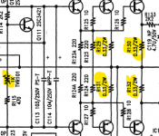
Can someone point out what resistor(s) I need to put voltmeter across from iaspire's schematic in post #5 above?
Not clear on which resistors are emitter resistors...
Thanks!!
Can someone point out what resistor(s) I need to put voltmeter across from iaspire's schematic in post #5 above?
Not clear on which resistors are emitter resistors...
Thanks!!
Idle current is the 0.33 ohm 2W resistors. But unless the amp is "hoarse" on soft sounds, I would not mess with them.
DC offset is servoed-out by IC101.
DC offset is servoed-out by IC101.
Thanks PRR!.....and...nice mask......
The amp has been a workhorse...usually on 10-12 hours a day for over a decade. I recapped the power supply a few years ago..caps were bulging.
I'll report back
The amp has been a workhorse...usually on 10-12 hours a day for over a decade. I recapped the power supply a few years ago..caps were bulging.
I'll report back
Ok..bias adjustment done.....
A couple of channels were down around 5-6mv.......Others were around 12mv
I attempted to adjust everything to 15mv or so and here's how it ended up:
Channels 5 and 6 had quite close matching voltage drop across each .33R resistor (less than .5mv)
Channel 4 had a 1.3mv spread from highest to lowest voltage drop
Channel 2 had a 1.5mv spread from highest to lowest voltage drop
Channel 3 had a 4.1mv spread from highest to lowest voltage drop
Chanel 1 had a 4.6mv spread from highest to lowest voltage drop
Since for each channel 1 pot affects 4 output FETs.....is this just an indication of how well the FETs are matched?? just curious.....
Attachments
- Home
- Amplifiers
- Solid State
- Bias on Parasound HCA-806A