Has anyone built the DIY Menno Van der Veen 70w or 100w tube amp which uses the Plitoron torroidal power and output transformers. I am thinking about using this design for my first tube amp project and was wondering what the DIYers out there have to say about this amp. My current system is bi-amped with 100W and 200w solid state amps with an active crossover. The tube amp would be used to drive two PHL 1240 mids and Raven R2 ribbon tweeter in a MTM with an overall sensitivity of abot 95 dB. I would use a 200w solid state for the 12" Lambda bass driver. The info on the Van der veen's tube amp can be found at Plitron.com. Thanks
Some 5 years ago I've built the 100W version.
I did substituted the EL34 with the KT66 from Valve-Art.
Until today I'm still very happy with this design.
Have look at my website.
Cheers
GeWa
I did substituted the EL34 with the KT66 from Valve-Art.
Until today I'm still very happy with this design.
Have look at my website.
Cheers
GeWa
I built the 40 w and 100 w Radio Bulletin versions a long time ago, EL84 and EL34,even had a talk with Menno once.
Both really nice amps, i did Menno's Mosfet 20 watt Class A amplifier too, also a design in Radio Bulletin.
Quite often the transformers are offered on the web here in Holland, the original Amplimo's(ILP).
I can not think of someone around knowing more on transformers and transformers for tube amplifiers than Menno van der Veen.
Many of the old transformer companies are gone, and a lot of the knowledge.
Even have a bunch of his articles in Radio Bulletin, including the ones on the 40 and the 100 watters.
Menno works for both Plitron in Canada and Amplimo here in Holland i think.
Yep - I built a pair just recently
I built the 100W versions using 4 x Winged C Svetlana EL34s.
I started off with them in Ultralinear Mode and found I had two problems.
Problem #1 - Slight bursts of HF Oscillation just after the postive peak of a sine wave. This was cured by increasing the 150R screen resitors to 1K. I reported this to Menno and he has put a note on his web pages to the effect that this mod should be "Standard".
Problem #2 - The Output Impedance of the basic amp (no global feedback) is 12 Ohms. There was some "colouration" of the sound as the output power followed the speakers impedance curve.
To cure problem #2 I rewired the output into triode mode. Output Impedance dropped to just less than 5 Ohms. Output power dropped to 40W BUT full power bandwidth is 12 Hz to 150 kHz
If you build the 70W version you can bias the output tubes a little higher and this will drop the output impedance to probably about 4 Ohms or just less.
In this arragement these mono-blocks have become my favourite amp(s). I have an 845 SET and a Hugh Dean AKSA 55 Nivarna Plus (Solid State) which these amps have displaced.
Have a look on the Photo Gallery above about the second to last page for the Gingertube "Menno Bricks" for some pics.
P.S. My speakers are VAF Research DCX s with a nominal impedance of 6 Ohms (95dB sensitivity). If your Speakers are less than 4 Ohms or if you are using Electrostatics then the Output impedance will probably be a bit high.
Oh - one last thing I pulled the 12AU7 and am using ECC99 in its place. I thought that gave me a slight improvement.
One problem with the design is that the Output Tube grid resistors are reasonably high and is in fact too high for anything except EL34s. Don't be tempted to use 6550s or KT88s. In any case the tube separation really only suits the skinny EL34s. I haven't checked data sheets to see if the KT66 that someone above suggested is a SAFE substitution or NOT.
I RECOMMEND that you use the "Winged C" Svetlana EL34s and not try to substitute cheaper alternatives.
I also did 2 other mods which I have no idea if they helped or NOT.
1) A 2uF/900V Polypropylene (from Rarefaction in Melborne Australia) directly across the high voltage at the Output Transformer Centre Tap connection to 0V.
2) A 100K 3W Metal Film bleed resistor across that cap.
I suggest that you put the electrolytic caps on the back (the tracks side) of the PCB just to keep them a bit further away from the heat of the tubes. Also put the bias pots and the bias measure resistors in each output tube cathode on the back of the board so that when the board is screwed down into its chassis you can get at the bias measuring points and the adjustments.
Due to the 250V AC Oz Mains Voltage my rail voltage was 480V instead of 450V so I backed off the OPutput Tube bias currents from 50mA to 45mA to keep anode dissipation at 22.5 Watts.
Good Luck
Ian
After thought
As an after thought -
100W or even 70W is WAY more than you need for driving Mids and Tops.
Have a look at Menno's UL40-S2 kit from Amplimo instead. Mennos web pages describe how to convert this design to his "Super Triode" configuration if desired.
Cheers,
Ian
As an after thought -
100W or even 70W is WAY more than you need for driving Mids and Tops.
Have a look at Menno's UL40-S2 kit from Amplimo instead. Mennos web pages describe how to convert this design to his "Super Triode" configuration if desired.
Cheers,
Ian
Has anyone built the DIY Menno Van der Veen 70w or 100w tube amp which uses the Plitoron torroidal power and output transformers.
Hi there........Yes...I've built one and never again..(this is only my opin)........I binned the toroidal output transformers....and redesigned the amp..using convential trannies.Why ? I found circuit unstable at low frequencies with massive amounts of 2nd harmonic thd and sloppy sounding mid....also output impedance sensitive.........hallmarks of a completely badly designed amp. Each toroidal o/p tranny (which had strip cores) had poor balancing circuitry which couldn't handle the steep sided BH curve when driven hard........resulting in skewed BH curve around the H axis. The bass sounded like a closet in it's finals.
Sorry to put cold water on your ideas !
rich
I love the post by richwalters (someone not afraid to say what he thinks about the emperor's new clothes)!
I have avoided using toroidal OPTs because (a) they're expensive; (b) I understand that they are easily prone to DC saturation if the OP tubes are not precisely balanced (even if they are balanced to start with, they probably won't be with the passage of time); and (c) they just don't look as nice, to me, as the more traditional E-I design.
I have avoided using toroidal OPTs because (a) they're expensive; (b) I understand that they are easily prone to DC saturation if the OP tubes are not precisely balanced (even if they are balanced to start with, they probably won't be with the passage of time); and (c) they just don't look as nice, to me, as the more traditional E-I design.
jacco vermeulen said:I can not think of someone around knowing more on transformers and transformers for tube amplifiers than Menno van der Veen.
He certainly is knowledgable on transformers... i had the opportunity to listen in on a couple conversations between him & Bill Perkins -- althou a lot went over my head, it was clear both of these guys knew a lot about transformers.
dave
It's never my interest to offend anyone......but when a <newamp design> designed in the last century turns up on my bench which has inbuilt inherent problems, I'm quick to flick it into a design that works........motto.....keep it simple. who wouldn't ??
rich
rich
UL40-S2 schematic
I have built the VANDERVEEN UL40-S amplifier.
I did not use any PCB but hand wired everything.
Up till now everything is working fine, very good sounding amp, impressive.
Only I have a little problem to bias out the last bit of 50Hz hum in the output tubes.
I heard that the new amp UL40-S2 has an adjustment for this...
Can anyone help me to find the schematic of this UL40-S2 amp?
tnx,
Frederik
Yes, but the mennosite does not have any schematics to download.
I have the schematic of the UL40-S (book Elektuur "Moderne high-End buizenversterkers).
The UL40-S2 has several mods that I would like to implement...
It seems to be difficult to find this schematic.
on the site of Menno Vanderveen I found some mods for the S2 but not a full schematic (incl. power supply, etc...)
It would be great if I could find it on this forum!
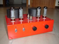
Attached an image of my self built UL40-S amp...
Many greetz from Belgium!
Frederik
I have the schematic of the UL40-S (book Elektuur "Moderne high-End buizenversterkers).
The UL40-S2 has several mods that I would like to implement...
It seems to be difficult to find this schematic.
on the site of Menno Vanderveen I found some mods for the S2 but not a full schematic (incl. power supply, etc...)
It would be great if I could find it on this forum!
Attached an image of my self built UL40-S amp...
Many greetz from Belgium!
Frederik
Attachments
VDV-3070 70W amp link
Have a look at Rudy's very detailed web site that describes building one of Meno's designs.
click DIY ZONE,
http://www3.sympatico.ca/r.godmaire/Home.htm
Rudy is very friendly.
cheers
paba
Have a look at Rudy's very detailed web site that describes building one of Meno's designs.
click DIY ZONE,
http://www3.sympatico.ca/r.godmaire/Home.htm
Rudy is very friendly.
cheers
paba
Re: UL40-S2 schematic
fit 1K screen grid resistors...see <screen grid mods> on Menno's site... click.. DIY kits...
perhaps this is the hum problem ?
..s............k ?......next one
rich
Only I have a little problem to bias out the last bit of 50Hz hum in the output tubes.
I heard that the new amp UL40-S2 has an adjustment for this...
fit 1K screen grid resistors...see <screen grid mods> on Menno's site... click.. DIY kits...
perhaps this is the hum problem ?
..s............k ?......next one
rich
Yeah, i sent a couple of e-mails some years ago and got some good help and he seems to be happy withe the opt's.Rudy is very friendly
I have had my heart set on the vdv-3070 for some years now (do a search and you'll see) but hade done some cheaper projects due to student-economy.
But if there's a problem with the transformers, why not just change brands to....whatewer you fancy, hammond, lundahl etc.? there isn't any problem with the design is there?
Comments on above
The comments above are useful.
The VDV70/100 is what I would call a "Concept Demonstrator" and not a final design. One of the reasons I suggested you look at the UL40-S2 instead.
Rich and Ray_moths comments about the DC balance when using Toroidal Output transformers is important, a final design should include bias servos to mainyain balance. I fiddle with my amp so much that DC balance is NOT a problem - I just check it and tweak if necessary every few weeks.
The other area where this "design" is a liitle weak is the "wimpy" phase splitter/driver. Substituting an ECC99 for the 12AU7 is a minor improvement (No other changes required).
The difference between the UL40-S and the UL40-S2 is that the phase splitter driver was changed from a 12AU7 common cathode amp with DC coupled concertina splitter to a 6N1P in the arrangement where the grid of the 2nd triode of the 6N1P is driven from an adjusted "Common Mode" point derived from a voltage divider off the outputs from the two anodes (Can't remember what that is called BUT its a common circuit method).
I don't believe Rich's claim about excess 2nd harmonic - I certainly don't notice it with the output tubes in Triode Mode. Although there was certainly something objectionable about the amp in Ultralinear Mode. Output Impedance is <5 Ohms in Triode Mode compared to 12 Ohms in Ultralinear Mode. I attributed the less than stellar performance in Ultralinear Mode to coloration introduced as the Output Power Curve follows the speaker Impedance vs frequency curve. Rich may be right and I might be wrong. Either way Ultralinear Mode is unacceptable with this amp.
The 1K Screen resistor mod addresses instability problems in Ultralinear Mode (also referred to by Rich). It has no effect on hum.
The whole rationale in using Toroidal Output Transformers is to address the problem of increasing 2nd harmonic distortion at low frequencies as the impedance of the output transformers primary inductance approaches the output impedance (rp) of the output valves (refer to articles by Partridge). The VDV2100 has a primary inductance of over 500H. Compare this to around 100H max for an EI transformer. Any problems with this will occur at a frequency 5 times lower when using the Toroids.
Note that putting the output valves into triode mode addresses this issue as well by lowering rp.
I'm perservering with Toroidal Output Tannies. Their Primary Inductance and Leakage Inductance values just CAN NOT be matched by EI Core Transformers. High Primary Inductance is essential for good low frequency sound quality. Low leakage Inductance is essential if you ever contemplate a global feedback loop.
Of course - if I was designing a guitar amp then I would make use of the limited primary inductance of an EI Core Transformer to deliberately generate plenty of 2nd harmonic at lower frequencies and would choose an EI Tranny with say 30 to 35H of Primary Inductance. A LOT of the older Valve HiFi Amps are like this and many people like the increasing 2nd harmonic at low frequencies. It makes the amp sound warm and subjectively much more powerfull than it realy is - too much of it however makes it sound "covered" or a littl "muddy".
Menno tells me that he is working on a new design to properly drive the Output trannies and accommodate all his various modes of Output - that is his Super Triode, Super Pentode various Cathode Feedback Schemes etc.
I'm not waiting - I'm happily using my 2 monoblocks in Triode Mode (with the VDV2100) while I blaze ahead with the design of a new pair of Monoblocks using VDV2100 CFB/H in Super Triode Mode (probably with KT88s instead of EL34s althogh I've got some matched quads of 6550s to try as well).
A bit of a "rave" typed together in a hurry BUT I hope there is something useful here.
PS for Bias Servo example look at "TENA - The Emporers New Amplifier" (alluded to above) on Norman Korens web pages.
Cheers,
Ian
Thanks for the very usefull info!
Do you have the schematic of the UL40-S2 phase splitter?
Greetz,
Frederik
Do you have the schematic of the UL40-S2 phase splitter?
Greetz,
Frederik
Thanks for the info. It looks like I will go the route of the UL40-S2. Where do I find a schematic for it?
Larry
Larry
EL 34 rewiring into triode mode
Gingertubes..
Have a El 34 100watt but like to improve the amps now..
you mentioned rewiring the output trafo of the 100Watt El 34 into triode mode. Is there a possibility to give some details how to do that which colours have to be connected or changed.. mail to me directly if you prefer that
Gingertubes..
Have a El 34 100watt but like to improve the amps now..
you mentioned rewiring the output trafo of the 100Watt El 34 into triode mode. Is there a possibility to give some details how to do that which colours have to be connected or changed.. mail to me directly if you prefer that
- Home
- Amplifiers
- Tubes / Valves
- Van der Veen 70W tube Amp DIY