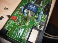
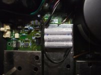
On the desk I have the above mentioned FM tuner from Linn.
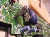
There is an oxidated area on the front PCB arround the 3V6 NiCd accu (memory cell) on the front PCB - go to the attachments so as to mpost #7 and #9 under
Linn Kairn repair
But the actually issue is the fact, this device has not been used for about 20-25 years. This means, that the electrolytic capacitors behind the rectifier must be soldered and reformed by a high-impedance resistor - go to
Reforming Electrolytic Capacitors
is there an other methody of this without the need to unsolder the big blue BHC caps ?
Thank you for advices.
Attachments
Last edited:
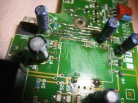
Linn did a really bad job here. I will change all electrolytic capacitors and of course the 3V6 NiCd accu but once the PCB without the caps & the accu battery I will clean all PCB and with a tester a measure for continuity in all oxidated area.
Linn did a really bad job here.
I have a Linn System from 20+ years ago. I would've done better keeping the Pioneer SX-838 receiver. (Turntable still works fine, however.)
Unfortunately I have no experience in this kind of reforming.The electrolytics can be reformed by bringing up the mains ac really slowly with a variac
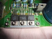
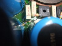
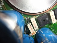
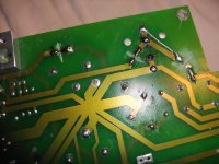
So I did it like this (the designation of the images can be found if you log out):
1) Cutting traces (conductor tracks) between rectifiers and electrolytic capacitors and between capacitors and voltage regulators
2) Introduce of 5K6 resistors between rectifiers and electrolytic capacitors
3) Removing resistors and attach jumpers at all performed cuttings
Attachments
-
 Linn Kremlin discon +22V cap-reg, +9V rect-cap.jpg996.4 KB · Views: 182
 -
 Linn Kremlin discon -22V, cap-reg.jpg1,004 KB · Views: 233
 -
 Linn Kremlin discon.&5K6, rect-cap, +22V.jpg985.8 KB · Views: 203
 -
 Linn Kremlin discon.&5K6, rect-cap, -22V.jpg991.3 KB · Views: 204
 -
 Linn Kremlin 5K6, rect-cap, +9V.jpg985.1 KB · Views: 180
 -
 Linn Kremlin reconnect +22V, cap-reg, +9V.jpg998.1 KB · Views: 181
 -
 Linn Kremlin reconnect -22V, cap-reg.jpg997.9 KB · Views: 195
 -
 Linn Kremlin reconnect, rect-cap, +9V.jpg982 KB · Views: 191
 -
 Linn Kremlin reconnect, rect-cap, +22V.jpg986.8 KB · Views: 183
 -
 Linn Kremlin reconnect, rect-cap, -22V.jpg981.4 KB · Views: 179
Last edited:
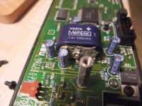
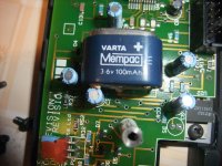
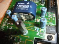
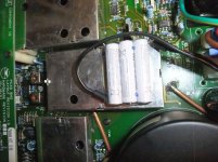
Replace back up Battery by other Version
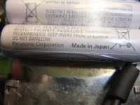
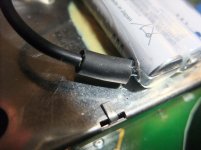
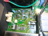
Concerning the 3V6 rechargeable battery I decided against keeping the genuine version, because one have no way to see the condition of the battery behind the metal cover.
Otherwise, the same was to be done as with the Linn KAIRN operating PCB - go to post #7 under
Linn Kairn repair
Concerning the 3V6 rechargeable battery I decided against keeping the genuine version, because one have no way to see the condition of the battery behind the metal cover.
Otherwise, the same was to be done as with the Linn KAIRN operating PCB - go to post #7 under
Linn Kairn repair
Attachments
-
 Linn Kremlin replace back up battery-I.jpg1,008.9 KB · Views: 176
 -
 Linn Kremlin replace back up battery-II.jpg989.2 KB · Views: 207
 -
 Linn Kremlin replace back up battery-III.jpg990.9 KB · Views: 157
 -
 Linn Kremlin replace back up battery-IV.jpg1,001.9 KB · Views: 170
 -
 Linn Kremlin replace back up battery-V.jpg995.7 KB · Views: 163
 -
 Linn Kremlin replace back up battery-VI.jpg1 MB · Views: 220
 -
 Linn Kremlin replace back up battery-VII.jpg985.3 KB · Views: 174
 -
 Linn Kremlin replace back up battery-VIII.jpg950.5 KB · Views: 191
 -
 Linn Kremlin replace back up battery-IX.jpg981.6 KB · Views: 211
Better to replace the caps than hack the board, and they will have to be replaced eventually anyway.
+1!
Reforming is just a loss of time and effort. They have had their useful lifespan and need replacement.
Reforming is just a loss of time and effort. They have had their useful lifespan and need replacement.
In the case of cheap caps that would be the better way. But here are caps in use from this series (successor of the brand "BHC/Aerovox"):Better to replace the caps than hack the board, and they will have to be replaced eventually anyway.
https://content.kemet.com/datasheets/KEM_A4020_ALC10.pdf
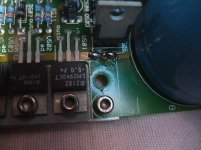
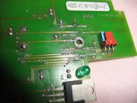
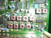
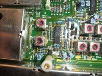
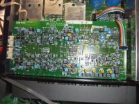
More images of this FM stereo tuner device:
Attachments
-
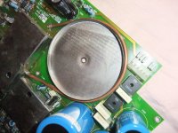 Linn Kremlin transformer area.jpg1 MB · Views: 230
 -
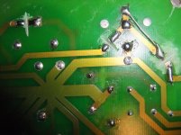
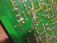 Linn Kremlin oxyd on solder joints.jpg1,016.2 KB · Views: 219
 -
 Linn Kremlin output buffer.jpg1,001.6 KB · Views: 217
 -
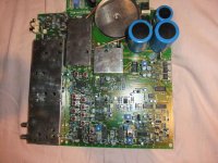 Linn Kremlin main PCB.jpg1 MB · Views: 282
 -
 Linn Kremlin IF 2xTDA1546.jpg1 MB · Views: 266
 -
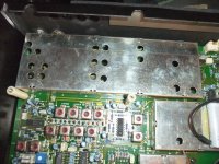 Linn Kremlin Front-End + IF-I.jpg1 MB · Views: 183
 -
 Linn Kremlin Front-End + IF-II.jpg1 MB · Views: 190
 -
 Linn Kremlin Front-End + IF-III.jpg1 MB · Views: 210
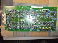
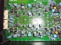
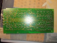
Stereo Decoder
Who can upload schematics, adjustment instructions so as the circuit description of the whole RF-IF section ?
Here the images of Stereo Decoder PCB:
Who can upload schematics, adjustment instructions so as the circuit description of the whole RF-IF section ?
Here the images of Stereo Decoder PCB:
Attachments
-
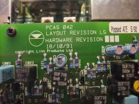 Linn Kremlin PCAS 042 stereo decoder-I.jpg1,021.4 KB · Views: 174
 -
 Linn Kremlin PCAS 042 stereo decoder-II.jpg1 MB · Views: 263
 -
 Linn Kremlin PCAS 042 stereo decoder-III.jpg1 MB · Views: 248
 -
 Linn Kremlin PCAS 042 stereo decoder-IV.jpg1 MB · Views: 202
 -
 Linn Kremlin PCAS 042 stereo decoder-V.jpg1 MB · Views: 171
 -
 Linn Kremlin PCAS 042 stereo decoder-VI.jpg1 MB · Views: 188
Last edited:
I've got one of these where the not so "Brilliant" power supply has crapped its pants and from what I have read they're none too reliable at the best of times.
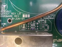
I have discovered that from the factory, they either came with a Brilliant supply (SMPS) or a toroidal transformer.
In a quest to get this unit back up and running I have decided to fit a toroidal as it will be more reliable than the not so Brilliant supply.
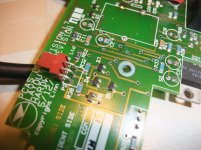
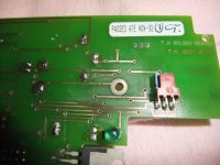
Linn have helpfully added instructions on the screenprinting to show which parts should be fitted when the transformer is used, which tracks should be cut etc.
However, there are some parts which are supposed to be fitted but they don't have any type numbers - just the generic 'U507' (a regulator, which I suspect is likely to be an LM317), D514, C526, Z515 etc.
I did contact Linn to see if they could supply me with the relevant info, the specific part numbers and values etc and they said as the unit was made end of line some 12 years ago they have no information.
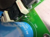
I need to determine the values/type numbers of various components, these being:
D514, D516 (probably just 1N4001)
C524, C525
C526
C527
R528
Z515
U507
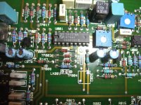
Any info that anyone can provide, even close up photos would be greatly appreciated!
I have discovered that from the factory, they either came with a Brilliant supply (SMPS) or a toroidal transformer.
In a quest to get this unit back up and running I have decided to fit a toroidal as it will be more reliable than the not so Brilliant supply.
Linn have helpfully added instructions on the screenprinting to show which parts should be fitted when the transformer is used, which tracks should be cut etc.
However, there are some parts which are supposed to be fitted but they don't have any type numbers - just the generic 'U507' (a regulator, which I suspect is likely to be an LM317), D514, C526, Z515 etc.
I did contact Linn to see if they could supply me with the relevant info, the specific part numbers and values etc and they said as the unit was made end of line some 12 years ago they have no information.
I need to determine the values/type numbers of various components, these being:
D514, D516 (probably just 1N4001)
C524, C525
C526
C527
R528
Z515
U507
Any info that anyone can provide, even close up photos would be greatly appreciated!
Attachments

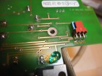
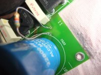
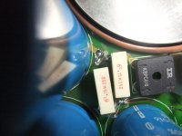
from my first image in post #11, you need several high-resolution samples from a smaller distance and different angles so that all the values of parts in question can be read.
In the mentioned image of me you can only see C523 (white MKT with 10nF and C529 (also white MKT with 220nF)
In the mentioned image of me you can only see C523 (white MKT with 10nF and C529 (also white MKT with 220nF)
The main disadvantages of Brilliant is the fact, that there is a lot of thermal stress inside because of lack of ventilation - check out this URL:IME Brilliants are serviceable, might be worth looking there first?
https://andydoz.blogspot.com/2019/01/linn-brilliant-power-supply-repair.html
and attached image in post #5 under
https://www.diyaudio.com/community/threads/help-with-a-linn-brilliant-psu-u25wsl.207507/
If you run a Brilliant 24/7 for 10 years it cooks. If you change the 85C rated cap in the start up circuit for a 105C and just turn the device on when you're using it perhaps the equation changes? In comparison to reverse engineering it back to a linear PS at least. Just thought it worth a look.
I hate SMPS at the best of times. As mentioned above, these ones suffer from zero ventilation - a sure-fire way to get electronics to fail, and from what I have read about these "Brilliant" supplies, they're not reliable at the best of times.IME Brilliants are serviceable, might be worth looking there first?
I've managed to reverse-engineer the circuitry used when the toroidal transformer is in place. It wasn't difficult. Now just one component to identify and even then I don't think it's strictly necessary for the operation of the unit.If you run a Brilliant 24/7 for 10 years it cooks. If you change the 85C rated cap in the start up circuit for a 105C and just turn the device on when you're using it perhaps the equation changes? In comparison to reverse engineering it back to a linear PS at least. Just thought it worth a look.
I want to be able to send this unit back to its owner and know that it will be reliable and go the distance. I have confidence in a linear power supply, I don't have confidence in the SMPS.
I would replace that battery with a 5v supercap about 1 cm by 1 cm.
The torrid supply is also lower noise
The torrid supply is also lower noise
- Home
- Source & Line
- Analogue Source
- Linn Kremlin FM Stereo Tuner