Sorry guys I have done tons of reading on here and a good few searches but I could do with a laymens introduction to the above topic.
I am getting keen to do an amp build over and above a small eBay board hanging off the back of my speakers!
I see a lot mentioned on this subject but I dont really understand it. We can all go to the hi fi store and buy 'separates ' and never hear this mentioned. So why does it become an issue the deeper we delve?
If anyone has a link to a good resource for absolute beginners on this subject would be great
Kind regards
Long story short... DIY Audio Articles
Take your pick, that site, in addition to being (very) long-standing, is also chock full of helpful, no-BS information, not to mention nicely-detailed projects 🙂
Take your pick, that site, in addition to being (very) long-standing, is also chock full of helpful, no-BS information, not to mention nicely-detailed projects 🙂
I see a lot mentioned on this subject but I dont really understand it.
This looks to be a good introduction.
https://www.electronics-tutorials.ws/amplifier/amp_1.html
Input impedance is how much the source component is loaded down by the
amplifier, hopefully not too much. Typical values are from 10k ohms and up.
A buffer circuit's main function is to have a high input impedance, and usually a low
output impedance. The output stage of a power amplifier can be considered as a buffer.
Sensitivity is the input voltage required for the amplifier to reach full output.
Last edited:
Let's put it in simple terms:
Am Op-Amp or Amp circuit usually has high input impedance and low output impedance. 10K to 8 Ohm for an AMP for example. Assume Low <1K. High 1-100K. Very high 100K to Megaohms.
If You feed a low impedance OUT to a high impedance IN circuit (called impedance bridging) all works because You are feeding from a high current capable device to a low current needing device. Think of a large water pipe (more Ampere) fed into a smaller one (Less Ampere). In Op-Amps we deal with mA of course.
If You connect the other way around, it doesn't work right because the input needs more current than the source can deliver, so You'll get that thin sound.
What You do is to insert a buffer between the two with a very high impedance 100K for example to convert it to low impedance to feed the other circuit, or You can use a buffer simply to isolate two circuits. For example You mix two signals and want to isolate the signals after the mix, otherwise the load could and would influence the mixing circuit.
Sensitivity is the minimum Voltage needed to achieve full power. Say an Amp has 1V Sensitivity means that if You turn the Volume knob all way up, With 1V it outputs nominal wattage or begin to clip. If You feed in 2V it will try to output double the power, but the amp will clip since power is limited by the PSU. If You feed In 500mW it will output half the power.
In terms of speakers, Sensitivity is the SPL measured at 1 meter when a speaker is fed with 1W. Don't confuse with Efficiency, often both terms are used interchangeably. Efficiency is the amount of power going into a speaker that is actually converted into sound. 99% of power is converted into heat or motion, not sound.
Start here and have fun Elliott Sound Products - The Audio Pages (Main Index)
I chose to link straight to the Articles page on that same site, which apparently has a far less... appealing title 🙂
Start here and have fun Elliott Sound Products - The Audio Pages (Main Index)
Thank you for all the considered replies.
It is a subject still on the fringes of my comprehension but I'm getting there!
Is it something that can be measured with a simple DMM and is there a window of given tolerance of acceptable variance between the power and pre?
Thanks again
It is a subject still on the fringes of my comprehension but I'm getting there!
Is it something that can be measured with a simple DMM and is there a window of given tolerance of acceptable variance between the power and pre?
Thanks again
You can not directly measure input and output impedance with a DVM.
You can rig up simple test scenarios to deduce approximate values and for these, and to do this you need a suitable signal source (sine generator or test CD/MP3 files etc) and a meter capable of measuring small AC voltages. You also need some variable resistors and a handful of assorted low value resistors.
If you add series resistance to an amplifier input you can find the value of resistance that 'halves' the output voltage from that amplifier. The value of your resistor that gives half voltage then equals the input impedance of the amplifier under test.
Measuring output impedance is a lot more difficult, particularly if the output is just an opamp stage. Usually the best method is just to look at the circuit and see if the designer has added any series impedance to the output sockets. If there is for example a series 100 ohm resistor then that alone pretty much sets the output impedance. If it has none and is just an opamp output direct to the outside world then the impedance is 'very low', perhaps just a fraction of an ohm.
Cheers that's a great help.
Any ball park figure to start with? I have some 10k linear potentiometers, is that the kind if variable resistor I could use?
Any ball park figure to start with? I have some 10k linear potentiometers, is that the kind if variable resistor I could use?
I don't mean to be a "rain on one's parade" kinda guy, but is there any particular reason you need or want to determine exact numbers? 🙂
No rain here! No probs. 🙂
Do I not need to know my amp and source are compatible?
I am very new to this.!
Do I not need to know my amp and source are compatible?
I am very new to this.!
Sure you do, although i'm not so sure too much equipment (outside the pro / semi-pro segment) actually specs input & output impedances all that often.
For example, some of the class-D chip-amps have varying input impedances, depending on what gain setting they're on, so... that can easily throw just about everything out the window. For example, the TPA3116 / TPA3118 has a 60kohm input impedance at the minimum (20dB, 10x) gain setting, but that goes as low as 9kohm, a bit over five times lower at the maximum (36dB, 63x) gain setting.
As with so many other things, it's somewhere between "the devil's in the details" and "it's how you use it" 😀
Adding a potentiometer in the mix can potentially be a case of throwing a wrench in the works (damn, i'm all proverb-y today). But i'll try to synthesize / "distill" some of the limited knowledge i have.
As far as the input of an amplifier is concerned, if one uses a potentiometer to attenuate the incoming signal, the source impedance it "sees" will have a maximum around the middle of the pot travel. At that point, that source impedance will be virtually half the nominal value of the pot (ie. 5kohms for a 10k pot).
You'll want to keep that value (the max source impedance) basically as low as you can, but a factor of, say, 2-3:1 to the amp's input impedance should suffice (as in, that max source impedance should be 2-3 times smaller than the input impedance of the amplifier).
At the same time though, you'll want to keep the value of the pot high enough so as not to present too low of a load to whatever's "upstream" of the amplifier. Most opamps are specified for a minimum load of 2kohms or so, with a few being capable of easily driving loads a bit lower than that (NE5532's good for 600ohm loads, for instance, or the NJM4560 easily drives 400ohms).
It's a bit of a balancing act, ideally you'd wanna hit that Goldilocks-zone, but at the same time, potentiometers are "only" E3 value series devices (ie. multiples of 1-2-5), so it's somewhat of a compromise at the end.
That being said, as Mooly above mentioned, most solid-state line-level stuff has relatively insignificant output impedances (pretty-much-zero up to 100ohm or thereabouts), so unless you're doing tube stuff, that should be of no (practical) concern either way 🙂
Cheers that's a great help.
Any ball park figure to start with? I have some 10k linear potentiometers, is that the kind if variable resistor I could use?
Typically you would need much higher than that. A preamp input impedance could be from 100k to 1meg, and a typical power amp while probably lower could still be in the 20k to 500k region.
It a getting a bit deep for me here!
I think I'll start by just connecting up and having a listen!
What are the symptoms of mismatched impedance?
I think I'll start by just connecting up and having a listen!
What are the symptoms of mismatched impedance?
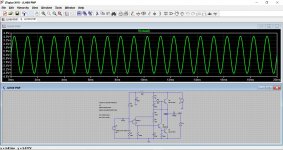
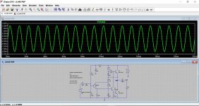
Here is a practical example, the JLH69 class A amplifier. The output has been set to some arbitrary value (4 volts peak here) and we then go on to add a series input resistor (R11) to see at what point the level falls by half. We find the value is around 50k which is no surprise because examining the circuit shows there are effectively two 100k's in parallel (R5 and R6) at the input. The upper one is returned to ground at AC by the action of C4.
In this case simply examining the circuit would give us a pretty accurate estimation without even having to test anything.
In this case simply examining the circuit would give us a pretty accurate estimation without even having to test anything.
Attachments

It a getting a bit deep for me here!
I think I'll start by just connecting up and having a listen!
What are the symptoms of mismatched impedance?
These days its pretty much unheard of to have any issues when matching solid state stuff. All solid state preamps are low output impedance and all solid state power amps have a high input impedance.
Problems... well it all depends on the circuit details. If a preamp has a coupling capacitor at the output then connecting it to a low impedance will cause the bass response to fall away because the cap + the low impedance it works into form a high pass filter.
If the preamp output were like the above and also from an intrinsically high impedance stage driving that coupling cap (such as a valve or non buffered amplifying stage then a few things would happen such as the level falling considerably, distortion could increase and the frequency response be altered.
Unless you are looking at exotic oddball gear its a non problem in practice.
Oh good....looks like I am looking into this too much then!
In short i have a Denon AVR that I am not overly happy with. It has preouts that I was going to use to initially power the stereo front pair with a class d amp and see if the sound improves.
I know there will be a lot of circuitry in the signal path so maybe can't expect big things. But I am happy to try. Admittedly the onbaord electronics do help with altering individual levels etc.
Thanks all once again.
The Denon will certainly have low output impedance 'preouts', probably lower than 100ohm.
So no problems 🙂
So no problems 🙂
I had "only" asked about this up in post #9... 😀
Oh good....looks like I am looking into this too much then!
In short i have a Denon AVR that I am not overly happy with. It has preouts that I was going to use to initially power the stereo front pair with a class d amp and see if the sound improves.
I know there will be a lot of circuitry in the signal path so maybe can't expect big things. But I am happy to try. Admittedly the onbaord electronics do help with altering individual levels etc.
Thanks all once again.
- Home
- Amplifiers
- Class D
- Please school me in input impedance / buffers/ sensitivity.