Hello!
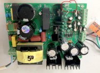
I bought this psu fo audio use on bay.
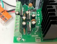
Does someone have an idea of the use of this "unused" connector ?
This seems connected to the controller board. No voltage on it. I was thinking to a place for a led ?
Cheers,
I bought this psu fo audio use on bay.
Does someone have an idea of the use of this "unused" connector ?
This seems connected to the controller board. No voltage on it. I was thinking to a place for a led ?
Cheers,
Attachments
Hello Stef1777, have you round any information about this connector ?
I have the same psu in 35v version.
Thank you, regards.
I have the same psu in 35v version.
Thank you, regards.

Hi Steff, be careful, the "connector" is not isolated from the primary supply! So take all the safety measures for checking!
There IS voltage across this connector.
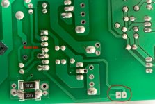
The SMPS is a quasi-resonant converter with two R740 (veery old but rugged) MOSFETs and the low side MOSFET of the switching bridge has a shunt resistor of 25mR connected. The voltage drop is used by the "black box" hybrid controller.
The voltage you measure at this "connector" is the shunt voltage! So when the supply is delivering power you will measure the Low Side Bridge Current there! Not really good for driving LED ;-)
I guess the black box contains a the good old L5699 IC.
The Power supply is very basic, no feedback and no PFC.
If you are interested about learning some basics, check https://www.nxp.com/docs/en/reference-manual/DRM119.pdf
Regards
Michael
There IS voltage across this connector.
The SMPS is a quasi-resonant converter with two R740 (veery old but rugged) MOSFETs and the low side MOSFET of the switching bridge has a shunt resistor of 25mR connected. The voltage drop is used by the "black box" hybrid controller.
The voltage you measure at this "connector" is the shunt voltage! So when the supply is delivering power you will measure the Low Side Bridge Current there! Not really good for driving LED ;-)
I guess the black box contains a the good old L5699 IC.
The Power supply is very basic, no feedback and no PFC.
If you are interested about learning some basics, check https://www.nxp.com/docs/en/reference-manual/DRM119.pdf
Regards
Michael
Last edited:
Hi,
i opened "black box" controller. Inside is sanded IC. Can you help me identify IC from schematic ? I used symbol IR2153 but this is not typical connection of this IC. I thing they used another IC.
Thank you


i opened "black box" controller. Inside is sanded IC. Can you help me identify IC from schematic ? I used symbol IR2153 but this is not typical connection of this IC. I thing they used another IC.
Thank you
Hi, also happened to me my "black box" burned out in this resource :-(
Did you find out what IC it is, please?
Thanks
Did you find out what IC it is, please?
Thanks
I have the same smps, and it had blown out without any load. I just wanted to check the voltage before I connect the amp board. The second smps board is ok, but it produce ±75V dc. (It should be ±65, but I have 245V ac with solar panels on my rooftop.) So I think ±75V is too much for my amp. Is there anybody who knows how can I correct the output dc voltages by replacing some parts? Thank you in advance! 😄
- Home
- Amplifiers
- Power Supplies
- HBP500 switching PSU connector