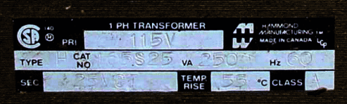
I aquired this amplifier. I have very little education and experience with electronics but trying to understand. I have not seen an amplifier design like this before. It is made by Foundation Research in Canada. I can not find info on it. The transformers are Hammond. Has a total of two Transistors 2N5684
I don't think It would be an easy sell so I'd like to use it for whatever it would be best at.
I have a few questions
1) Could you point me to a lesson on this type of amplifier?
2) Is this a good quality amplifier?
3) Does this design have any specific strengths ( clarity, decibels, bandwidth ) or weaknesses.
Thanks
Attachments
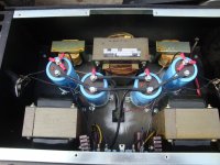
It could be some kind of single ended amp with inductive loading of the output transistors (those two smaller transformer/coils) in place of lossy resistor loading.
It could be some kind of single ended amp with inductive loading of the output transistors (those two smaller transformer/coils) in place of lossy resistor loading.
Says me while not even noticing the 'output' transformers at the front. Same applies though, single ended.
D'accord. Those big trannies with even bigger air gaps appear to be SE output trannies.
Best regards!
Best regards!
Input transformers are most probably voltage step up followed by emitter followers . If so, this amp needs low impedance preamplifier.
Do you mean those little irons next to the power tranny? I think it clearly can be seen that these ain't no input step ups, but PSU chokes instead. It is hard to get the DC power supply that quiet as a SE amplifier demands without choke(s) or active regulation.
Best regards!
Best regards!
Stereo, single ended for sure:
Center top is the power transformer, and on both sides are one PSU filtering choke per channel, it's pretty clearly visible from how the 4 filter caps are connected, and a bridge rectifier on the bottom plate.
On the bottom left and right are definitely either chokes or output transformers, though, from the thickness of the wire on the power transformer, I'd say the supply voltage is fairly low and the chokes are in parallel with the load - though, perhaps it's an auto-transformer deal.
The size of the choke/transformr suggests a good power output, 20-30W?
It seems very well thought out as far as layout.
Yes more pictures! Front & rear panel, more detail on where those big black transformers connect, etc.. A model number might help too. 🙂
I concur, it looks like some kind of single ended, transformer loaded output.
** the right hand connection to the board in the lower center of the picture (yellowish wire) looks like it's barely connected, if at all. Beware before turning on the power. Maybe you should use a bulb tester to power it up?
Hmmm... Power transformer says 25V center tapped. 250 VA.
Could this be a version of le Monstre?
Could this be a version of le Monstre?
Emitter followers do not require clean power supply and far less chokes which limits current variations .
This amp looks to be the single ended version of Susan Parker's feedback less push-pull amplifier.
Thanks I will try to get more pics. So. Most of the comments go way over my head. Is this a good amp? Is this the type that would rum high impedance speakers well? Based on the design what are it;s strengths if any? I haven't really checked it out. The first thing I noticed was the missing fuse inline with mains so I am anticipating a short circuit or high load somewhere. One of the Transistors was replaced, sloppily I might add. I think the original is Motorola and the replacement is NTE.
argonrepublic,
My guess is it's not an amplifier. It looks more like two switching power supplies with two series pass regulators in one box. the two transistors I am guessing are series pass elements. If my guess is right, it may have been used to power an amplifier. If there is no inputs connections and only what appears to output connections, it is almost certainly a power supply.
Regards, Mickeystan
Please. Post more photos of the amplifier. I can't find ANY information about this amplifier online, so any information we'll have to work on will come from more photos of the inside and outside.

Last edited:
Please. Post more photos of the amplifier. I can't find ANY information about this amplifier online, so any information we'll have to work on will come from more photos of the inside and outside.
It wouldn't be mysterious with photos... ☺
- Home
- Amplifiers
- Solid State
- Mystery Amplifier