Hi Everyone. I am hoping someone on here has some suggestions on what to troubleshoot here. Last week I picked up a harman kardon a300 that is in nice shape. It was recapped a couple years ago and looks to be a professional job. The issue I am having is that it is making a hum/buzzing noise that comes out of both channels. The volume control has no effect on it, and it is there on each input. It is fairly quiet as it gets covered up when any music is playing. The pre-amp tubes have been replaced with a matched set. I found that one of the original power tubes was microphonic so I replaced them with a matched set as well and I still get the noise. I have also checked the grounds and cannot find any issues. All the resistance values in the chart on the schematic test good. I believe the hum is 120hz. Any ideas on other things to check?
Thanks
Thanks
Attachments
Replaced or not, the PSU 'lytics could have dried out.
FWIW, I'd replace the doubler stack caps. with 220 μF. parts and double the 1st decoupling cap. to 100 μF. Modern 'lytics are much more volumetrically efficient than the old twistlok parts. Install a CL-130 inrush current limiter in the red/white line, to tame turn on surges,
Replace the OEM doubler diodes with low noise UF4007s.
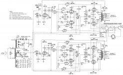
Check V5, the 12AU7/ECC82. The unbypassed cathode of the concertina phase splitter is subject to filament to cathode leakage.
Connect a 1 uF cap from V5 Pin 2 to ground, and another 1 uF cap from V5 pin 7 to ground. If that does it, then remove the caps, and replace V5 recent production JJ ECC82s (has a spiral filament).
If it still has the hum, then replace V4 12AX7/ECC83 with a recent production JJ ECC83s (it has a spiral filament). You did say that the hum was still there when you turn the volume down, that means the problem is after the volume control, unless you have a ground loop on the volume control.
What is left could be B+ filtering. There is lots of open loop gain in the 12AX7, and Pentode wired 7408 stages. If B+ has too much ripple, negative feedback will not get rid of the effect of all of that B+ ripple.
I had a brand new A300 (brand new parts), and it had hum. There was not only low frequency hum, it sounded a little like a drill motor interference. Is that about what your amp sounds like?
I have another 12au7 on hand and tried it, no difference. I also have 2 new JJ ECC83s, I put them in V3 and v4, no difference. For the test, does it have to be a 1uf cap? I think I have some 12 and 30uf caps on hand.
I replaced the original volume control with a modern replacement due to one channel not working on the original. hum was present with the old one. The hum does not change volume based on the volume control. It is always there, even when turned all the way down.
The 40/40/40uf cap has been replaced with 3x 47uf caps which should be fine. But the 100/50/200 cap has been replaced with 100/47/200 uf caps. So C24B is currently 3uf short. Is that an issue? I would still think that should be within tolerance?
Also, the diodes test out fine, still a good idea to replace them?
Thanks
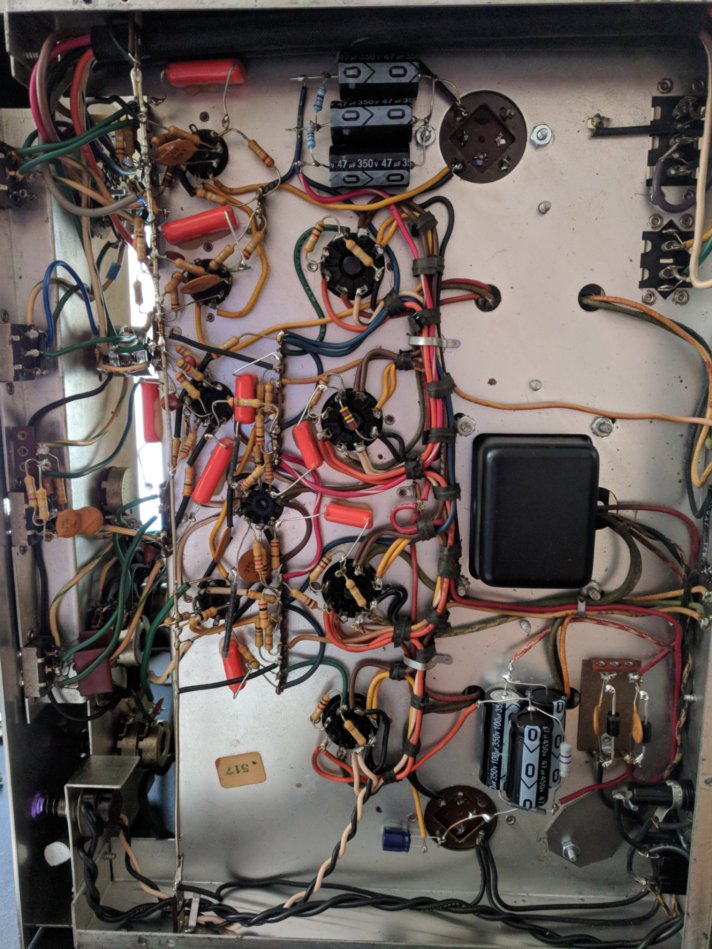
Here is a pic of the underside.
I replaced the original volume control with a modern replacement due to one channel not working on the original. hum was present with the old one. The hum does not change volume based on the volume control. It is always there, even when turned all the way down.
Replaced or not, the PSU 'lytics could have dried out.
FWIW, I'd replace the doubler stack caps. with 220 μF. parts and double the 1st decoupling cap. to 100 μF. Modern 'lytics are much more volumetrically efficient than the old twistlok parts. Install a CL-130 inrush current limiter in the red/white line, to tame turn on surges,
Replace the OEM doubler diodes with low noise UF4007s.
The 40/40/40uf cap has been replaced with 3x 47uf caps which should be fine. But the 100/50/200 cap has been replaced with 100/47/200 uf caps. So C24B is currently 3uf short. Is that an issue? I would still think that should be within tolerance?
Also, the diodes test out fine, still a good idea to replace them?
Thanks
Here is a pic of the underside.
Attachments

Caution! Be very careful when working on this amp. It does not have bleeder resistors on the B+ voltages (a very bad thing!). The capacitors will hold a charge for a long time after the amp is turned off and unplugged.
How much hum do you have? How efficient are your loudspeakers? Can you measure the hum at the amp loudspeaker terminal with a DMM?
To simplify, you can do these tests on one channel, and make conclusions. Whatever test below reduces the hum in one channel will likely do that for the other channel. But then you can repeat the test for the other channel to be sure.
1. The amp uses 20k (0.02uF) coupling caps that are connected to the 1 Meg Ohm resistors, and to Pins 2 and 7 of the 12AU7. That is where you need to connect the cap to, and connect the other end of the cap to ground. Do not use 12uf or 30uF (or any other electrolytic cap). The 12AU7 will not stabilize quickly; also the 12uf or 30uf caps may have way too much leakage for the 12AU7 to bias properly (do not use electrolytic caps). Instead of the 1uF cap I suggested earlier, you could use 0.1uF or 0.2 uF caps at pins 2 and 7, with the other end of the cap to ground. (like a cap that is used for coupling cap duty). After testing for hum, remove those caps to restore the circuit to normal. If that did not eliminate the hum, then on to step 2 . . .
2. Do this test with your loudspeakers disconnected, then use a 10 watt 16 Ohm load resistor on the 16 Ohm tap, or a 10 Watt 8 Ohm load resistor on the 8 Ohm tap. You will need to measure the hum across the load resistor with a DMM, or scope with a 1X probe. Measure the hum, and write it down. Locate the 1k Ohm resistors that are connected to pin 5 on the 7408 output tubes. The other end of the 1k Ohm resistors connect to the junctions of 470k Ohm resistors and the 0.05uF coupling caps. These junctions are where you will connect a wire to ground. Then Re-measure the hum on the load resistor with the DMM, then remove the shorts to ground to restore the circuit to normal. If there was the same hum when the 1k Ohm, 470k Ohm, 0.05uF junctions were shorted to ground, that means you either have too much B+ ripple, or that your 7408 tubes are not well matched at the particular operating voltages and currents of your amp, or both (B+ ripple, and tube match).
B+ If you replace the doubler 100uF caps with 200uF or 220uF, it will double the I(squared) heating in the power transformer high voltage secondary will increase. You might try and use 150uF caps there, if the 200uF makes the power transformer run too hot. I do like the idea of doubling the 50uF cap with a 100uF cap (the one that powers the 7408 screens).
Changing V3 as you did can not reduce the hum that is still there when you turn the volume control all the way down, because the output of V3 is Before the volume control.
Last edited:
This isnt my first tube amp project, but I am still new at this and need better testing equipment. My multimeter isnt sensitive enough to check the hum. I can tell you that through speakers that are somewhere around 85-88db the hum is noticeable but pretty quiet. Through my Klipsch Heresy's it is very noticeable, those are 96db. Does that sound normal? If not, I will order some caps and try to find some better testing equipment. I would really like to find a nice meter and a oscilloscope as I really enjoy doing this stuff.
Thanks!
Thanks!
I use a Fluke handheld DMM that reads down to 100uV hum (a lot less than the hum you have).
The reason I suggested using 16 or 8 Ohm dummy loads was to be able to remove the loudspeaker load. Never test an amp without some kind of load, either speaker, or load resistor (power resistor, a 5 watt or less resistor is not going to 'cut it'). In test # 2 of my post # 7, there is a very remote possibility that the pentodes might oscillate. Use the loudspeakers as the load, try the test on one channel at a time, and be prepared to turn the amp off if it oscillates. If it does not oscillate, you will be able to hear if the hum went away.
The reason I suggested using 16 or 8 Ohm dummy loads was to be able to remove the loudspeaker load. Never test an amp without some kind of load, either speaker, or load resistor (power resistor, a 5 watt or less resistor is not going to 'cut it'). In test # 2 of my post # 7, there is a very remote possibility that the pentodes might oscillate. You can use the loudspeakers as the load, try the test on one channel at a time, but be prepared to turn the amp off immediately if it oscillates. If it does not oscillate, you will be able to hear whether the hum went away or not.
Yes, it sounds like your amp may have about the same level of hum as the one I had on my then new A300 of almost 50 years ago.
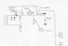
If I had that amp today, I would be tempted to re-design the B+. It would have an added 25 Ohm 10 Watt resistor, and an added 50uF 400V cap.
I am attaching my schematic of that B+ modification.
The reason I suggested using 16 or 8 Ohm dummy loads was to be able to remove the loudspeaker load. Never test an amp without some kind of load, either speaker, or load resistor (power resistor, a 5 watt or less resistor is not going to 'cut it'). In test # 2 of my post # 7, there is a very remote possibility that the pentodes might oscillate. Use the loudspeakers as the load, try the test on one channel at a time, and be prepared to turn the amp off if it oscillates. If it does not oscillate, you will be able to hear if the hum went away.
The reason I suggested using 16 or 8 Ohm dummy loads was to be able to remove the loudspeaker load. Never test an amp without some kind of load, either speaker, or load resistor (power resistor, a 5 watt or less resistor is not going to 'cut it'). In test # 2 of my post # 7, there is a very remote possibility that the pentodes might oscillate. You can use the loudspeakers as the load, try the test on one channel at a time, but be prepared to turn the amp off immediately if it oscillates. If it does not oscillate, you will be able to hear whether the hum went away or not.
Yes, it sounds like your amp may have about the same level of hum as the one I had on my then new A300 of almost 50 years ago.
If I had that amp today, I would be tempted to re-design the B+. It would have an added 25 Ohm 10 Watt resistor, and an added 50uF 400V cap.
I am attaching my schematic of that B+ modification.
Attachments
Hmmm (pun intended)…
Most "buzz" in this Old DIYer's opinion is generated up front at the rectification stage. Those pesky diodes generate the grating zzzzzzz; the purpose of the following capacitor-resistor-capacitor-resistor-capacitor chain is to successfully high-cut-filter the harmonics of rectification away. The “furthest-to-the-left” (toward input) stages need the cleanest DC power, hence their tap is also furthest to the right on the power supply CRCRC chain.
But the oft under-appreciated issue is that that Buzzzzzzz isn't just a bit of 2×F (i.e. 2 × 60 Hz = 120 Hz), no. It is significantly pulse-y. Somebody (Dirac?) came along with the idea that mono-polar pulses are equal to the exponential sum of all harmonics (even and odd) in the frequency domain. Wicked.
But if you think on that for more than a few milliseconds, the light bulb goes off… Hmm! The harmonics extend from audio-frequency all the up to the radio-frequency!!!
Yep. Hence why designers of late work so diligently to squash the same harmonics from being generated, the spikes, to begin with. Because all the little wires running thru the chassis of the amplifier are also little antennae, picking up spurious RF.
Bad RF.
Bad.
But how best to do this in practice?
As any of my august co-authors might list,
• short wire lengths
• ultra-fast recovery diodes (… or … tube rectifiers)
• ferrite beads on the rectifiers
• very fast quenching capacitors
• low value series resistors before the diodes (horrors!)
• chokes near the front-end. with short legs.
Tho' the advice so far has been “double the caps in the volt-doubler and first reservoir”, this actually may not solve the problem, but make it more severe… driving higher peak amperages from the secondary of the power transformer creates higher diode cut-off switching noise at voltage reversal. Maybe its time to consider a smallish but good inductor? I think so.
Seriously tho': the situation with rectifier switching noise is probably the source of the Buzzzzzzz. And that needs to be addressed at the source. Never underestimate the Buzzzzzzz quenching power of a bit of series resistance in FRONT of the doubler diodes.
GoatGuy
Thanks guys. I will be ordering some parts today.
GoatGuy, are the uf4007s a good choice for diodes or do you suggest something different? Also, what value resistor do you recommend to try infront of the diodes?
GoatGuy, are the uf4007s a good choice for diodes or do you suggest something different? Also, what value resistor do you recommend to try infront of the diodes?
They're good. Very good. Worth consideration.
ALSO worth consider… see those caps in parallel to the rectifiers?
They should have series-resistances added of 220 to 470 Ω, each.
Sucks up more spike that way, more safely. Without ringing.
GoatGuy
ALSO worth consider… see those caps in parallel to the rectifiers?
They should have series-resistances added of 220 to 470 Ω, each.
Sucks up more spike that way, more safely. Without ringing.
GoatGuy
GoatGuy,
I agree. I never did like voltage doubler rectification. Although it saves the expense of 1/2 of the B+ secondary windings; it does so at the expense of the degree of difficulty to get quiet performance of the B+. Some other manufacturers used it successfully. But I suspect that they reduced the real estate 'aperture' of the current loops of the B+ secondary, diodes, and 2 doubler filter caps; and that they did not include any other B+ circuitry on that loop. When not implemented properly with attention to details this is both: an electromagnetic radiator, and a ground loop waiting to happen.
I do not like capacitors across the diodes, that is a good way to slow down the turn off of a fast turn off diode. But the idea of using a resistor in series with the cap should help. But I would rather use a fast 2kV diode and no diode bypass capacitors.
I once had a B+ that was blowing out the diodes. Then I replaced the original diode types with 16A 1200V HEXFRED diodes in a full wave B+ supply (center tapped secondary), and built a quiet supply. Of course the HEXFREDs are expensive, but simplicity saves time and money. I am sure there are other better diode solutions, but the HEXFREDs worked.
I also advise that the B+ transformer also have filament windings that are used (loaded by filaments), to help de-Q the B+ secondary. You end up with primary windings terminated by the power line (not very good, but better than nothing), and the secondary filament windings (resistive termination). The primary becomes unterminated when the power is switched off, unless there is a capacitor across the power switch.
I do not recommend using a transformer that only has a B+ winding, unless RC snubbers are added to the diode circuits.
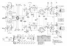
A well executed voltage doubler is fine. The A300's implementation is not particularly well done. Taking O/P tube B+ off the doubler stack is "Cheap Charlie". The H/K Cit. 2 shows the correct method, which is a choke between the doubler stack and a reservoir capacitor. If the doubler stack caps. are made especially large, a refinement is the insertion of a "hash" filter between the doubler stack and the main filter choke. Scan the archives here and at AA for my detailed explanation that refers to Fourier's Theorem.
The "hash" filter idea applies anytime large valued cap. I/P filtration is employed.
The "hash" filter idea applies anytime large valued cap. I/P filtration is employed.
Attachments
A well executed voltage doubler … on Harman Kardon Citation 2 … is a thing of beauty.
Aesthetically, you just have to love those old fashioned circuit diagrams. Easy on the eyes; nice wiggly windings on the transformers, clear color codes, easy-to-follow wiring with big black dots on wire crossings and great annotation for the "viewpoint" of the metering switch. All black-and-white, suitable for Xeroxing a million times.
Sigh… respect…
GoatGuy
I believe the Marantz 8B B+ was another successful (quiet) implementation of a voltage doubler.
Chokes and Hash chokes are great. But they do take up real estate, have weight, and are expensive. Be sure to keep them away from where their magnetic fields can radiate into all the other wiring, and to other laminations. They can also talk through a steel chassis to other laminations (old heavy amps usually used steel).
The capacitance of a doubler cap pair is effectively 1/2 of either of their uF rating. Full wave is full capacitance, but requires 2X the voltage rating (but is 1 part, not 2).
I prefer full wave rectification with a center tapped primary that has double the voltage. When possible, I like to use choke input (with the choke properly located, and properly oriented versus output transformers and, if present - interstage transformers. Choke input has lower transient currents than capacitor input (transient currents on the High Voltage secondary are also transferred to the filament windings and core laminations (and have a noisier magnetic field, and noisier ground loops; all with higher amplitude high frequency components). Choke input B+ filters has lower I(squared) loss than cap input B+ filters. The power transformer windings run cooler.
But all designs are a tradeoff.
Last edited:
The capacitance of a doubler cap pair is ½ of their individual μF value. Full wave is full capacitance, but requires 2× the voltage rating (but is 1 part, not 2).
Yep. Series C's:
CTOT = C₁ • C₂ / (C₁ + C₂)
Which, for C₁ ≡ C₂ becomes
CTOT = C²/(2×C) … cancel common C's
CTOT = C/2
CTOT = C/2
I prefer full wave rectification with a center tapped primary that has double the voltage (and) choke input (choke properly located versus output/interstage transformers. Choke input has lower transient currents than capacitor input (transient currents on the High Voltage secondary are also transferred to the filament windings and core laminations (and have a noisier magnetic field, and noisier ground loops; all with higher amplitude high frequency components). Choke input B+ filters have lower I² loss (in transformer ≡ heating) than capacitor input B+ filters, thus running cooler. … But all designs are a tradeoff.
We agree to some degree. I like what might be called “critically low C-input” power supplies. Let me explain. For all intents and purposes, when one designs an amplifier, it isn't terribly hard to pre-compute the maximum continuous B+ current flow. Figuring 50% higher than continuous for peak current flow gives a number IMAX. Since I use CLCXC — where X is an active regulator - filtering almost exclusively, the “center C” has a voltage which ideally doesn't wiggle very much. But between the C₁ and C₂ is definitely a ΔV voltage. Say it is 20 volts. And that peak amps is 400 mA. I then compute in the 8.3 msec (10 msec Europe) window, the capacitance required to drop no more than 2× that ΔV. 40 V.
Using
ΔV = It/C … which inverts to
C = It/ΔV … subbing in values
C = 400 ma × 8.3 msec / (2 × 20 V)
C = 0.4 × 0.00833 / 40
C = 0.0000833 F
C = 83 μF
C = It/ΔV … subbing in values
C = 400 ma × 8.3 msec / (2 × 20 V)
C = 0.4 × 0.00833 / 40
C = 0.0000833 F
C = 83 μF
Now at least one has a “napkin value” for the value of C₁. And surprise, surprise, it is a value which is pretty much consistent with what we find in top-of-the-shelf audiophile amplifiers like the Harman Karmon Citation II.
Surprise, surprise.
GoatGuy
I too sometimes use a 'modified' choke input filter.
If I have a transformer with too low of a secondary voltage to use choke input (too low for the B+ voltage I need), I use a 1 to 4uF cap before the choke.
1 uF capacitive reactance at 120Hz is 1326 Ohms. A 100mA load will have 132V peak to peak ripple, and then the choke takes the peak voltage from the rectifier, minus the average of the peak to peak ripple. Starting with solid state rectifiers, and a 350 - 0 - 350 Vac secondary, 350V x 1.414 = 495V peak. The center of 132 Vpp ripple is 66V. 495V - 66V = 429V after the choke. There would need to be a much larger capacitor after the choke to get the ripple down. The choke is swinging 132V peak to peak, quite a bit less magnetic spray than a choke input supply which swings 495V peak to peak.
If I had used choke input instead, and the same 350 - 0 - 350 Vac secondary, we would get 350 x 0.9 = 315V DC. But the choke would be swinging 350 x 1.414 = 495V. The choke input supply would have considerably more magnetic spray than the cap input supply above that uses the 1uF before the choke. And more capacitance at the choke output, and at least one RC filter stage after the choke would be needed to get the ripple voltage as low as needed.
6A3sUMMER, in your experience, at approx. what value of capacitance does critical current behavior cease and cap. I/P filtration behavior start? FWIW, I'm reasonably confident that pseudo choke I/P filters will retain critical current behavior, when the "fudge factor" part is below 1 μF.
Eli Duttman,
I believe choke input filter, and cap input filter are well defined. But there is a region where it does not fully follow the characteristics of either one.
Suppose I have a power transformer secondary voltage that can not produce the B+ voltage I want, because it is between the voltage output of either a choke input supply, or a cap input supply. In that case, I use a 'modified' choke input supply that uses a small cap at the input (that cap is the 'modification'), I do 3 things:
1. I start with a choke value that meets the critical inductance criteria (inductance versus load current), just as if the power supply was a real choke input supply.
2. Starting with the secondary peak voltage x 1.414 (minus any rectifier drop), I find how much more voltage I need to drop that will give me my desired B+ voltage. Lets say the voltage I need to get rid of is 50V. I will need the input peak to peak ripple voltage to be 2 x that (2 x 50 = 100V) (100V peak to peak ripple)/load current = Xc, capacitive reactance at 120Hz. I solve for the capacitance. 1/(Xc x 2 x pi x 120 Hz) = C
3. I calculate the resonance of the input capacitor, C, and input inductor. 1/(2 x pi x (root of (L x C))). If the resonance is near to 120Hz, I will not use that combination. A 1uF cap, and 5H choke has a resonance of 71 Hz, that is OK for 120Hz full wave.
But suppose I need to use 0.5uF to get the B+ voltage I need: A 0.5uF cap, and 5H choke has a resonance of 100.7Hz. I will not use that combination, it is too close to 120Hz. I can keep the 0.5uF cap and get the B+ voltage I need, but I need to change to a 10H choke to get the resonance back down to 71 Hz.
I hope that convoluted process makes sense.
Last edited:
@ bandit88
let the pro have fun with each other 😉
me problematic is that the guy who recapitulated your A300 has used
the old mass point of the old capacitors, that's what I had done too at the beginning and I was hummatic.
I recovered insulated terminals screwed on the chassis to make my mass taps and since it is almost silent.
- Home
- Amplifiers
- Tubes / Valves
- Harman Kardon A300 Buzz/hum