A number of people have contacted me requesting service info schematics ect to to aid in restoration or repair of these amplifiers the company went into liquidation in the late seventies but the amplifiers still have an avid following
I thought i had lost this information but it recently surfaced after sifting though some papers that had been boxed up during a shift.
I felt it best to post them here for others to accesss i hope these will be of value.
I thought i had lost this information but it recently surfaced after sifting though some papers that had been boxed up during a shift.
I felt it best to post them here for others to accesss i hope these will be of value.
Attachments
Rait 60/60 Amp
Hi,
Have had said amp for decades in storage as it kept blowing some round disc things on the back. I'm hoping your post might assist in my new found enthusiasm to get it working again !
Many thanks,
Aub.
A number of people have contacted me requesting service info schematics ect to to aid in restoration or repair of these amplifiers the company went into liquidation in the late seventies but the amplifiers still have an avid following
I thought i had lost this information but it recently surfaced after sifting though some papers that had been boxed up during a shift.
I felt it best to post them here for others to accesss i hope these will be of value.
Hi,
Have had said amp for decades in storage as it kept blowing some round disc things on the back. I'm hoping your post might assist in my new found enthusiasm to get it working again !
Many thanks,
Aub.
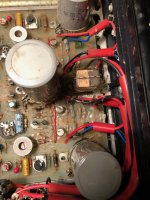
Following on from this thread, I have a Rait 60-60 preamp and power amp I bought in the 70's. Unfortunately smoke poured out of it recently and I found the circuitry covered in a white rubbery material. A number of resistors have blown apart (someone had put 3A fuses in before I got it). I have the circuit diagrams but I'm having quite a bit of trouble identifying which components are dead. Two questions: (i) does anyone know if there are pcb layouts available anywhere for the power amplifier, and (ii) what is the white stuff? Could that have come out of one of the large electrolytic capacitors? It appears to have sprayed everywhere including on the underside of the top cover. If you look carefully at the photos you can see the white stuff on the right in the space between the circuit board an the power transistors' heatsink.
Thanks,
James
Thanks,
James
Attachments

A number of people have contacted me requesting service info schematics ect to to aid in restoration or repair of these amplifiers the company went into liquidation in the late seventies but the amplifiers still have an avid following
I thought i had lost this information but it recently surfaced after sifting though some papers that had been boxed up during a shift.
I felt it best to post them here for others to accesss i hope these will be of value.
Hi P.Allen,
Thank you for posting the schematics for the RAIT pre/power amplifier combo.
I just happened to be working on a friends RAIT 30-30 Power Amplifier and have had to replace a noisy input transistor 40361 (NPN).
Would you just happen to have any advice on correctly setting the 200K bias preset that controls the biasing of the 40361 input transistor please?
(The schematics appear to be silent on this bias setting.)
Thanks,
Alex.
Attachments
Hi Alex,
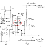
That pot would be used to center the amp output at the junction of the two 0.22ohm resistors at mid supply, i.e. ~30 to 35VDC.
Bias of this amp is interesting. The amp has flat gain down to 0Hz, making it sensitive to base-emitter drift of the 43601 input stage. The BC107 transistor near the pot generates a temperature sensitive bias to compensate.
Cheers!
Hi BSST,
I thought the same but, I'm not sure that I agree with your comments on the thermal tracking as the transistor setting up bias voltage to the input transistor is not the VBE multiplier and appears to be configured as a current source, albeit that will probably drift with ambient temperature inside the unit - given the biasing arrangement, but the two BJTs (43601 & BC107) are not thermally coupled together - something that I have seen in other similar circuit typologies that follow the original concepts outlayed by RCA in the late 1960's early 1970s with some of their audio amplifier application notes.
What I have found is when I set the input bias trimmer so that the junction of the two output device emitter resistors is sitting at 1/2Vcc the THD distortion, at 1 kHz, is around 0.12%, and the clipping is not symmetrical.
Setting the trimmer to around 61% of Vcc gives a THD @ 1kHz of better than 0.05%. But now the junction voltage is far from 1/2 Vcc and clipping symmetry is poor.
I'm guessing that RAIT may have had some practice of setting the trimmer to a compromise position that traded off clipping asymmetry vs THD performance?
Alex
Hi Alex,
I just thought bias was interesting--- but not necessarily well executed. Nominal DC gain from input stage to output is 1k5/68+1 or about 23. Similarly, gain to base-emitter drift of the BC107 is about 22k/1k +1 , also about 23. Assuming Vbe drifts 2.2mV/Celsius, both circuits would drift about 50mV/Celsius. But the 200K pot, 22k and 47k degrade the nominal match. And as you note, the devices aren't thermally coupled either. 50mV/C drift hardly seems worth addressing with 60V B+.
Re optimum THD not being well centered: you might confirm the 47uF bootstrap cap is working. An open cap would produce these symptoms, though I imagine THD would be worse than you're finding.
Best,
Steve
Hi Alex sorry I don't catch up with this thread often Steves comments on the amp are all correct.
The only thing I would add is if the regulator is OK at idle but for some reason failing under load it would definitely result in the asymmetrical clipping you have observed.
I would measure the supply under load with a scope this should give you clues as what the fault is if the regulator is the problem.
I hope this helps.
Regards Peter.
The gunk I see spread over the board and components, looks very much like clear silicone sealing compound. i.e. building glue and it seems to have been applied with a brush. I can't think of a sensible reason why anyone would do that to electronic circuits unless they thought there was a moisture or corrosion problem. Maybe it was a weird notion that smothering a problem fixes it or perhaps that the thermal drift problem could be reduced this way? Anyway, I think it causes its own problems that only get worse over time and, of course, its now virtually unrepairable.(ii) what is the white stuff? Could that have come out of one of the large electrolytic capacitors? It appears to have sprayed everywhere including on the underside of the top cover. If you look carefully at the photos you can see the white stuff on the right in the space between the circuit board an the power transistors' heatsink.
Thanks,
James
Last edited:
Almost an exact copy of Bailey 30W. Was a good amplifier in its time and working models still are.
Hi All,
I have started work on the 60-60 power amplifier. One of the output coupling capacitors exploded out through its base. The white gunk everywhere was the dielectric from the electrolytic capacitor. It's taken out a number of resistors as well. Not sure what the cause of the mishap was, and with all obviously damaged components replaced, it's blowing the 2A DC fuse when powered up. Any hints on where to start looking?
I have started work on the 60-60 power amplifier. One of the output coupling capacitors exploded out through its base. The white gunk everywhere was the dielectric from the electrolytic capacitor. It's taken out a number of resistors as well. Not sure what the cause of the mishap was, and with all obviously damaged components replaced, it's blowing the 2A DC fuse when powered up. Any hints on where to start looking?
Well, I'd start at the beginning as they say. Is the power supply functional without any amplifier connected?
It's running a rectified 60V so generates approx 90V on the input capacitors. It uses 40327's and a 2N3053 in the PSU which my oancient RCA databook says the 40327 has a 300V Vcer spec - overkill perhaps - but the 3053 was only a 40V device. Admittedly the 3053 should not see high voltages but I'd never use one in a supply like that! (My own 50-50 amp uses 2N3440's in those positions and 3773 regulator (but also a 3441 driver for higher pulse currents) as it has a 140V rating).
But first- without the PSU connected do you get 90V without things blowing up?
Then check the PSU out (don't forget to check the discharge resistor across the caps first. 90V caps can cause quite a bang if shorted).
If the PSU does not work I'd be tempted to redesign while rebuilding. Not a technique favoured by some, but when a circuit is not (in my view) optimum...
Not sure what the SJ5492 devices were. Would have recommended 2N3716/2N3792 as replacements but like the original Bailey amplifier (MJ481/MJ491) they're obsolete. At a push modern epi 2N3055/MJ2955 would work (as I have used in my 50-50).
- Home
- Amplifiers
- Solid State
- Rait Amplifier service information