Dear all
I stumbeled across a couple of russian UHF triodes, small ceramic tubes
- ГС-14, GS-14
- ГС-4, GS-4
- 6C17K, 6S17K
These seem to be very linear triodes, working at moderate voltages, direct heated.
Does anybody know anything about their use in tube amplifiers? They could be used for the preamp stage probably.
Thanks for your answers.
Thomas
The 2 major problems with most RF ceramic tubes is:
1. You have to get special sockets. Or make your own.
2. You have to take special care to keep your circuit from oscillating.
UHF tubes are sensitive to long, medium, and short connection wires, because at UHF it only takes an inch of wire or so to become a medium or high inductance at UHF. That inductance resonates with the stray capacitance and tube capacitance, and now you have a UHF oscillator, instead of an amplifier.
Many classic oscillator circuits may be formed by just connecting the UHF tube up for audio use. Colpitts, Hartley, etc. are intrinsic with just the wires, and tube and stray capacitance.
Grid stoppers, Plate parasitic RF chokes (resistor with a few turns of wire wrapped over the resistor), Beads, and other techniques, or combination of these may kill the oscillations.
And you will find it hard to determine if there is a UHF oscillation or not.
Just probing the circuit may stop the oscillation, but it will start up again when you disconnect the probe.
I am not saying you should not use UHF tubes, I have often considered using these kinds of tubes (especially the triode versions).
Someone in another thread on this forum asked for the lowest noise triode. I voted for the type 416 lighthouse tube. This months MJ Japanese magazine (March 2018) has a stereo preamp that uses type 416 tubes.
It's pretty easy to solder directly to the 6s17k triode if you clean the silver plating with an eraser first.
In these coaxial Russian tubes the best to my know to Home Audio is the GI-7BT a Triode used in Ham Radios with forced air cooling by fan, seems a great tube 12V/2A huge Dissipation 350W(maybe in pulse) and inexpensive.
''GSTube.com''. Tubes, sockets etc. Search result for <u>gi7b</u>
http://www.mif.pg.gda.pl/homepages/frank/sheets/018/g/GI7BT.pdf
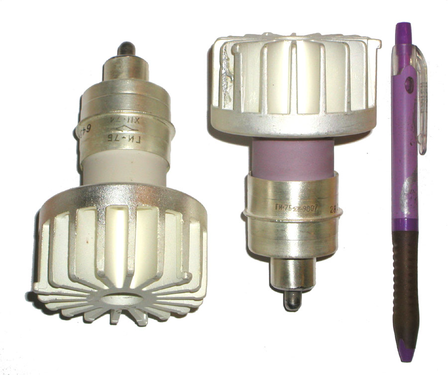
Please Note its Not the Microwave version:
http://www.mif.pg.gda.pl/homepages/frank/sheets/018/g/GI7B.pdf
''GSTube.com''. Tubes, sockets etc. Search result for <u>gi7b</u>
http://www.mif.pg.gda.pl/homepages/frank/sheets/018/g/GI7BT.pdf
Please Note its Not the Microwave version:
http://www.mif.pg.gda.pl/homepages/frank/sheets/018/g/GI7B.pdf
6S17K tubes have zero microhhonic effect, they supposed to work on accelerations up to 60g in missiles. It has high mu and high gm. The payback, is grid current. Around 100 NanoAmp. Enough for a grid bias.
Also, filament is connected to cathode, so filament power source has to be pretty clean.
I bought bunch of them (they are hard to match), to use in phono and microphone premps, but still have no time to play with them.
Also, filament is connected to cathode, so filament power source has to be pretty clean.
I bought bunch of them (they are hard to match), to use in phono and microphone premps, but still have no time to play with them.
Thanks a lot for all these feedbacks.
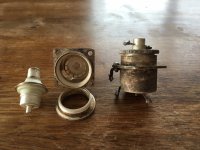
The socket question is partly solved, I have a pair of original GS-14 sockets from Lithuania. They completely contain/cover the tube, nothing left to see than the anode cap.
I tend to build the sockets in my own, so that the tubes are visible, clamped by the contacts, no soldering.
What I see in the feedbacks is the potential risk of catching and amplifiying RF signals, right? This might be controlled with short wiring, grid stoppers, parasitic chokes...
Could you post a photo of the sockets and also where you bought them from. I have used them and love them for the clarity of their sound. Glass input tubes seem microphonic now.
When I tried soldering them, they stopped working. In addition they seem to be susceptible to heat so need to be well ventilated.
Audio ratbag: The heart attack special - 6S17K-V powerdrive GK71 SE amplifier
ray
When I tried soldering them, they stopped working. In addition they seem to be susceptible to heat so need to be well ventilated.
Audio ratbag: The heart attack special - 6S17K-V powerdrive GK71 SE amplifier
ray
When I talked about RF, I was referring to the possibility that the tube would oscillate, and Create RF (which probably would also cause additional distortion of the audio).
I was not talking about the possibility of the tube picking up RF.
Depending on the environment and design, even a 12AU7 might pick up RF.
Yes, that would require a very high level RF field, and poor shielding, no grid stopper, etc.
I have been in such high level RF fields that even a Simpson VOM picked up RF without even connecting the leads to anything.
When I talked about RF, I was referring to the possibility that the tube would oscillate, and Create RF (which probably would also cause additional distortion of the audio).
Why would they?
Contrary, UHF tubes have lower parasitic capacitances and inductances, so less likely to oscillate, because they are UHF tubes. But since they have high transconductance, they can, so gird stoppers help.
Some one has built amp with GI-7b
https://www.nataudio.com/products/vacuum-tube-power-amplifiers/item/96-microwave.html
https://www.nataudio.com/products/vacuum-tube-power-amplifiers/item/96-microwave.html
We have to connect to the tube using wires.
At 1 GHz, a 2 inch wire might be about 20nH, that is about 125 Ohms of inductive reactance.
At 1 GHz, 1 pF is 159 Ohms of capacitive reactance.
Hmmm, are we getting close to resonance?
At those frequencies, a couple of 2 inch connecting wires 'side by side' is an air transformer.
If you combine fuel, oxygen, and enough heat, you have a fire.
in a similar manner, if you have gain, resonance, a certain phase, and feedback, you have an oscillator.
Design an oscillator, and get an amplifier.
Design an amplifier, and get an oscillator.
'Nuff said?


Sorry to say, but I have no clue what you are showing, I am 70+ and I cannot even see what your DMM adjustments are.
Data about Ia at different Uak and Ugk settings would be appreciated.
Also grid leak current, especially near zero -Ugk would be interesting.
Data about Ia at different Uak and Ugk settings would be appreciated.
Also grid leak current, especially near zero -Ugk would be interesting.
Last edited:
Hi.
The working conditions were 1150V anode at 90ma. Cathode resistor bias regulated with 100W potensiometer. As I remember the -Ug was about -15 -20V. I have not measure the grid leak. ( I will do it to my next test). The tube begs for higher voltage.
I will try it again with 1500 to 2000V where the -Ug could be higher.
Hello Dimitrios,Hi!
Another test with UHF russian ceramic 6S17K-V and GS13 GS-13 audio SE amp can be seen on my youtube channel "Dimitris Bel" YouTube
Comments are welcommed.
regards
Dimitrios
Do you have a schematic for this 6s17k - gs13 amp?
Best regards ,
Marc
Belgium
Hi.
The schematic is basic.
There must be fixed negative to the screens becouse the cathode is conected to one filament.
I have a new version with four parallel single ended at 100ma and 6s53n nuvistor as driver which works very very good. I will post photo and test later to you tube.
Now I sent you the scematic.
regards
Dimitrios.
- Home
- Amplifiers
- Tubes / Valves
- Russian UHF amplifier tubes