From all outward appearances the practice of installing a cap of a higher rated voltage seems to be acceptable, especially if you are not deviating from the original values too much. I have done it with small caps as I am sure much of you have as well. Increasing capacitance is something I have not done though. I know changing capacitance can have adverse affects on the sound chain but I would hope that increases in the capacitance of the main power supply caps would do no harm and could possibly do some good.
I have looked at some engineering sites and in most cases those writing on the topic would accept this practice as long as the replacement values were not ridiculous and always greater, never lower.
I am working on a very crusty SAE A202. It is tired and I just want to give it a second life. I have done a similar rebuild on a 502 and was delighted with the final outcome.
Like the A502, the 202 uses odd-ball size caps which are not available and have no direct replacement due to the space constraints. The A202 uses 63v, 10000uf caps. I will not be able to source those. However I have new 502 caps that are rated at 80v 15000uf. The 502 cap is taller but the diameter and triple pin connections are identical. I installed these larger caps in the A202 with only the need to notch a bracket to make room for the additional height. I have not powered it up yet. It is in pieces as I wait for a shipment of smaller signal caps.
So my ultimate question is, does anyone see a problem with the increased capacitance put into this circuit? My instinct tells me it will be okay. I am already fully committed to the idea as I have performed the swap but since I have yet to power it up I cannot really tell what the outcome will be. I would like to bounce this off of some of the more technically savvy folks here. There may some part of the science of capacitance I am missing here. I once learned this when omitting snubber caps in a motor control circuit. Some of the math is above my head 🙂
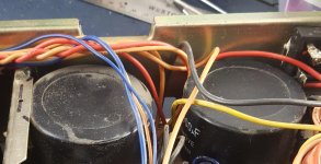
Here is before and after:
ORIGINAL CAPS

SIZE COMPARISON

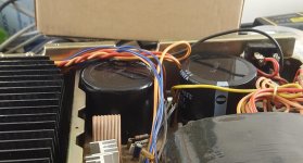
BRACKET MODDED & NEW CAPS INSTALLED

Thanks for the insight.
I have looked at some engineering sites and in most cases those writing on the topic would accept this practice as long as the replacement values were not ridiculous and always greater, never lower.
I am working on a very crusty SAE A202. It is tired and I just want to give it a second life. I have done a similar rebuild on a 502 and was delighted with the final outcome.
Like the A502, the 202 uses odd-ball size caps which are not available and have no direct replacement due to the space constraints. The A202 uses 63v, 10000uf caps. I will not be able to source those. However I have new 502 caps that are rated at 80v 15000uf. The 502 cap is taller but the diameter and triple pin connections are identical. I installed these larger caps in the A202 with only the need to notch a bracket to make room for the additional height. I have not powered it up yet. It is in pieces as I wait for a shipment of smaller signal caps.
So my ultimate question is, does anyone see a problem with the increased capacitance put into this circuit? My instinct tells me it will be okay. I am already fully committed to the idea as I have performed the swap but since I have yet to power it up I cannot really tell what the outcome will be. I would like to bounce this off of some of the more technically savvy folks here. There may some part of the science of capacitance I am missing here. I once learned this when omitting snubber caps in a motor control circuit. Some of the math is above my head 🙂
Here is before and after:
ORIGINAL CAPS
SIZE COMPARISON
BRACKET MODDED & NEW CAPS INSTALLED
Thanks for the insight.
Attachments

Looks good. I’ll bet that any extra load on the rectifier won’t hurt since that’s not a lot more that you are adding.
I have a 2300 to recap that I have been avoiding as it looks like it is built like a safe, and not fun to disassemble.
I have a 2300 to recap that I have been avoiding as it looks like it is built like a safe, and not fun to disassemble.
From a performance point of view it should be fine. They will put a larger load (demand for current) on the transformer and rectifier diodes as they charge and may also cause the fuse to blow if it's close rated
Good point about in-rush current. I did not consider that.
Thank you both.
When I get it assembled I will put an amp clamp on the AC line and record the in-rush.
Right now there is a fast acting 6 amp fuse in there.
I guess I could put a 6.3 or 7 amp fuse in there if needed.
Or would it be better to put a Slow-Blow 6 or 6.3 fuse in there?
Who knows, it may be fine with the existing fuse. If I can temporarily jam it together and power it up today I will test the draw.
Thanks!
Just as a follow up:
I put the 202 on a variac. The minimum turn on voltage was approx 70vac.
I let it sit there for about an hour to make sure nothing else was going to blow up. I also kept a low value fuse in the variac.
I bought it as "working" but I don't have any real history on it so who knows what surprises it had waiting!
After an hour I shut it down, removed the variac, and let the main caps bleed off for a few minutes. Once they were under 0.1 volts I switched the amp back on while an amp clamp was attached near the main fuse.
The peak current I read on the amp clamp during turn-on was 1.4 amps.
I think this is low enough to be safe with a 6 amp fuse.
Anybody disagree?
The running current with no audio was .09 amps.
The running current with audio was 1.5 amps (800Hz sine wave set to produce an output of approx 25 watts into 8 ohms).
Thanks!
...The peak current I read on the amp clamp during turn-on was 1.4 amps....
Unless you know better: an amp-clamp may not follow the very brief charge-up surge, and not give the very peak of the current.
However I see no problem with what you have done.
I even suspect the designer originally penciled something like the caps you used, and got foiled either by production cost or simple lack of space.
an amp-clamp may not follow the very brief charge-up surge, and not give the very peak of the current.
Yes this is true especially with lower priced clamps. Specialty clamp meters like the Fluke 335 & 336 attack this specific problem with proprietary filtering and sampling algorithms. Unfortunately I have a cheaper Mastech 2108A so yeah I may be missing the true peak. I think a buddy of mine has a 335 so now I am really curious to do a comparison. Thanks for your input!
Unable to adjust bias on SAE A202
I am wrapping up re-cap of this amp. It is functioning. DC offset was way out of alignment. I was able to dial that in just fine now. As I was doing that I noticed the heat sinks were very cold even though the amp was powered up for a long time. The amp is passing audio on both channels. I moved on to dial in the bias, put meter on emitter resistors and observed absolute zero change in bias if the bias pot is moved. I tried it on both channels and the same.
So I poked around on the individual amp sections looking for a failed part. There is not much on each channel board; the bias pot, a few caps, two zeners, a diode and a few resistors and output devices. Basic tests show these parts to be ok. There is a NTC thermistor tied directly to the bias pot. There are no markings on it. Just a glob of yellow epoxy mounted to a screw terminal. I took it out of the circuit and measured approx 12meg ohms at 98 degrees. That seemed unusually high to me. It does vary in resistance if I apply heat to it.
When these devices go bad what is the typical failure mode? Do they change their scale dramatically? I looked at a table of the various NTC thermistors made by Ametherm and none of those had readings in the MegOhms at 98F.
I do not have a parts list or schematics for this device. I don't have a reference on what room temp resistance should be. If this part is a temperature compensation device then it might explain why moving the bias pot has no effect. Any ideas or hints?
...There is a NTC thermistor ...measured approx 12meg ohms at 98 degrees....
That is what keeps happening in my Chevy. The ECU sees >1Meg (but not infinity; that would be error) and thinks it is -40 degrees, floods the engine with fuel.
That is what keeps happening in my Chevy. The ECU floods the engine with fuel.
Oh, that's not good for fuel economy for sure. Just do what I did to fix that. Get a Chevy Bolt EV.
But now that I think of it, if the thermistor goes bad in my motor controller that could be a lot more ugly, with a lot more smoke 🙂
This is a 3/4-ton snow-plow. There's not enuff wire on the street to do it electrically. Not quite enuff snow to justify a Diesel (though they are common here). Classic Chevy gas V-8 with the TBI from the 1990s.
If your bias sensor screws into the water jacket, NAPA has the part on the shelf. They must fail a lot. I've become sure the GM part is the naked thermistor sealed in a bung. Unless the fault is GM's bung, my guess is these sensors DO go bad often enough.
If your bias sensor screws into the water jacket, NAPA has the part on the shelf. They must fail a lot. I've become sure the GM part is the naked thermistor sealed in a bung. Unless the fault is GM's bung, my guess is these sensors DO go bad often enough.
There's not enuff wire on the street to do it electrically.
I don't know about that. I work for Anheuser Busch, who coincidentally just placed a large order for some Tesla electric freight trucks. These things can pull a full 84,000 lb load at highway speeds for @ 500 miles, and have ridiculous torque and acceleration for a truck. I don't see how this could be a problem pushing around a little snow

This would be my 2nd electric car. The first was an i3. I swear no sports car can keep up with me at takeoff. I have no tranny, no gears to change, just what seems like an infinite RPM range as it is basically direct drive with a reduction gear.
But I digress; this thread has gone way off topic. Perhaps we can move it to the DIY electric car section when someone realizes that the motor controllers are basically 3 channel amps with 350 volt DC power rails.
Back to the matter at hand....this dang thermistor. I wish I had another 202 to compare it with.
I am going to build an robotic slapping machine and program it to slap me all night long. I am here chasing ghosts. It turns out the thermistor is not a thermistor. It is actually a diode that is somehow being used for thermal compensation. How do I know this you ask? IT SAYS IT RIGHT ON THE BOARD. I feel like a total idiot. I noticed that there were polarity markings for the entry points of the sensor. I was asking myself why would there would be +/- marks for it. Then I look at the designator "D201", and I just about fell out of my chair. This is what I get for making assumptions.
Now I wonder if that is still available?
At least you figured it out!
Another reason I am avoiding working on my later unit; the schematic I have looks like it was made with a crayon.
At least you figured it out!
Another reason I am avoiding working on my later unit; the schematic I have looks like it was made with a crayon.
I had two threads that kind of crossed and touched topics on this SAE amp I was working on. I am posting my conclusions to put this thread to bed.
I copied the following text from the other thread.
I realized I left this thread sort of hanging with no conclusion.
So here is the condensed version.
I really wanted to understand what was going on with this amp, not just fix it.
So I painstakingly reverse traced the entire amplifier assembly and created a working virtual model of it in SpiceLT. This included both the input board and amplifier boards.
I never used circuit simulation software before so there was a learning curve there. I got the main gist of it learned over a weekend.
As a reminder there are no known A202 specific schematics available. There are schematics for the larger A502 which does biasing temp compensation differently.
Now I have the entire schematic drawn by my own hands. With that in hand I could compare virtual voltages to the real voltages on the physical unit.
The root cause of the problem was a resistor that had wandered way out of spec. I had to pull that resistor out of the circuit to discover that.
I also upgraded the Toshiba output transitors to Sanken equivalents. The Sankens are slightly larger and have higher current capability but match the rest of specs.
I learned quite a bit from this amp and I have a better grasp of what is going on, at least with this design.
That is what keeps happening in my Chevy. The ECU sees >1Meg (but not infinity; that would be error) and thinks it is -40 degrees, floods the engine with fuel.
Off topic but my Subaru had problems like this. I remember it threw a code saying the thermostat was open. I had driven it a few miles in 30 deg F weather and it was giving hot heat, so I knew it wasn't stuck open. The sensor socket was defective; you could wiggle it and the car would run fine. I got a new socket from a company called Aeromotive (I'll find the website if you want) and fixed some computer grounds too.
You can measure it too. I actually put test leads in the wire harness to monitor it. Remember to check for voltage drop from sensor ground to wire harness ground. You know, just like an audio amplifier. 😉
This stuff is way easier than audio electronic equipment. It's meant to be serviced in the field by trained technicians. If you can do audio electronic equipment, then you can do this.
Trying to revive this old thread... reading through this, I'm also having the same thing going on with my SAE A202, can't seem to get an idle current reading (zero volts) and cold cooling fins yet the amp sounds really good at all levels. Did you ever figure this out?Unable to adjust bias on SAE A202
I am wrapping up re-cap of this amp. It is functioning. DC offset was way out of alignment. I was able to dial that in just fine now. As I was doing that I noticed the heat sinks were very cold even though the amp was powered up for a long time. The amp is passing audio on both channels. I moved on to dial in the bias, put meter on emitter resistors and observed absolute zero change in bias if the bias pot is moved. I tried it on both channels and the same.
So I poked around on the individual amp sections looking for a failed part. There is not much on each channel board; the bias pot, a few caps, two zeners, a diode and a few resistors and output devices. Basic tests show these parts to be ok. There is a NTC thermistor tied directly to the bias pot. There are no markings on it. Just a glob of yellow epoxy mounted to a screw terminal. I took it out of the circuit and measured approx 12meg ohms at 98 degrees. That seemed unusually high to me. It does vary in resistance if I apply heat to it.
When these devices go bad what is the typical failure mode? Do they change their scale dramatically? I looked at a table of the various NTC thermistors made by Ametherm and none of those had readings in the MegOhms at 98F.
I do not have a parts list or schematics for this device. I don't have a reference on what room temp resistance should be. If this part is a temperature compensation device then it might explain why moving the bias pot has no effect. Any ideas or hints?
Last edited:
- Home
- Amplifiers
- Solid State
- Installing larger main caps in A202 frame