Good evening gents, after having had a set of Hammond 1650R in my parts drawer, alongside all the parts I ordered for a KT88 push-pull amplifier, I figured it is time to finish this project. However I need some help with determining whether the 1650R would even be suitable for what I'm trying to do.
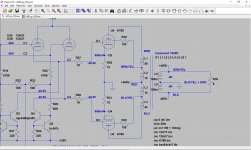
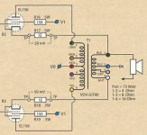
The design I've drafted is somewhat less than conventional, as I'm using a full symmetrical/balanced design, all the way down to the output transformer. Please see the attached schematic for reference.
I'm aiming for 8R secondary impedance and I'm hoping I can get away with what I have in mind. Basically I'm starting from the 16R configuration, but am grounding the center point (BLK/YEL+GRN) and am taking feedback (-NFB and +NFB) from each of the respective end points of these windings.
By doing this, would I have enough current drive capability for 8R or would I need to consider a different configuration of the transformer's secondary windings? Or would this not be recommended all together, and if so, why not?
Attachments
So the primary sees 2.5k? That might be a bit tough for the KT88’s. You’ll better off doing the following (with some mods to suit your FB scheme) with the 8R tap and 0V (note it’s not grounded).
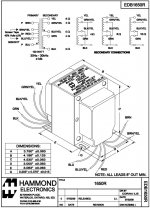
Well, the info on the 1650R datasheet is somewhat ambiguous; you'll notice they parallel two 4R windings crosswise, for 4R use, which has me scratching my head. And then they subsequently hook the same windings up, end to end, for 16R use. And their 8R implementation appears to use a different tap/winding all together? It is all a bit confusing for a transistor guy like me.
Typical Hammond wiring, so if you put a 8R load across 16R/0V, the primary will see about 2.5k, which is too low.
Right, this is standard secondary wiring for this type of Hammond output transformer.
What Hammond did is make two independent secondaries:
Thus:
What Hammond did is make two independent secondaries:
- One at 4 ohms
- One at 8 ohms with a 4 ohm tap
Thus:
- Two 4 ohm secondaries in series = 16 ohms.
- Two 4 ohm secondaries in parallel = 4 ohms but at higher current
- Two 4 ohm secondaries in parallel (= 4 ohms) in series with the remainder of the second secondary = 8 ohms.
What someone else did with Hammond's independent secondaries, so can you:
a) Two 4R in parallel and the rest between of 4-8 goes for the NFB. Not bad idea to add 100R 1Wa to it to slightly load the amp when the speaker is disconnected, or
b) same layout with 4R feeds the woofer, and the 4-8 stretch feeds tweeter - works for bi-wiring, but
in both cases you watch the polarity; the ground must go to the center tap of the 8R section.
And also to note, the stretch between 4 and 8 has an impedance of 0.686 ohms, so 4 ohms in series with 0.686 ohms = 8 ohms.
I've approached this differently for now, as with a 4R impedance the net primary is at 5K again, so that works.
That's weird, i look to use hammond 1650k on a dynaco st-70 with 6l6. how i can do that? Regards.
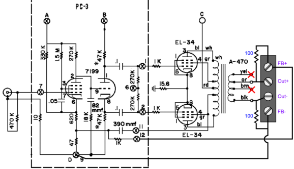
Could you post the full circuit. 12at7 might be better for driver as the grid cathode voltage will be lower and the bias on the output stage less susceptible to this variation.
1650K is 3.4K, would be 6.8K to to 8 Ohms using 4 Ohm output taps. BUT, you'd give up an octave of low-frequency response - feedback will give it back, saturation won't be a problem, but low-frequency phase shift MAY be an issue for stability.
OK if you are wanting differential feedback but only have the 1650R what about using a potential divider on the output for one of the FB legs? OK the speaker output will not be properly balanced. So wire the two 4R windings together ground the bit between the 4R and 8R.
The schematics is the same as reply#2 and here's le link for the transformer. I will use a modified board to use 6GH8 instead of the rare 7199 and 6BG6 instead of EL34 because i had 4 NOS of these tubes in hand.
Hammond Mfg. - "Classic" Push-Pull - Tube Output Transformers - (1608 - 1620, 1645 & 1650 Series) So i use the 4 ohm hookup and use the 8 ohm tap for NF and a 1 ohm resistor will do the rest. Great, i will start building without worries. Thanks.
Hammond Mfg. - "Classic" Push-Pull - Tube Output Transformers - (1608 - 1620, 1645 & 1650 Series) So i use the 4 ohm hookup and use the 8 ohm tap for NF and a 1 ohm resistor will do the rest. Great, i will start building without worries. Thanks.
Last edited:
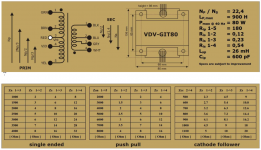
Alright, I just had another idea and am wondering whether this could work? Menno Van der Veen uses the 4-8-16 Ohm winding for CFB, cathode feedback, on his VDV-GIT80 transformer and I’m wondering whether I could do the same with the Hammond 1650R? Becauss I always end up with a headache if I have to think about combining transformer windings could any of you skilled professionals give me a hand here to figure this out? Please find the hookup for the Van der Veen transformer attached, as well as the datasheet for the Hammond 1650R.
Attachments

100% feedback to the output valves' cathodes is only about 1 to 2dB - maybe worth doing if easy, but not worth losing sleep over if not easy. With these earlier design Hammonds it's not easy.
Lately they've changed to a "conventional" all series output connection, probably because folks were getting confused. It's not as tightly coupled for 4Ohm use, but better for 16Ohm, and a wash for 8Ohm.
If you're feeding back to a higher impedance location, and not running significant DC through the secondary windings, it's not really necessary to directly ground any tap in order to make a push pull feedback signal. You can make a "Y" with, say, 50R resistors to ground, from the 8Ohm and 0Ohm taps, and feed back from those taps.
All good fortune,
Chris
- Home
- Amplifiers
- Tubes / Valves
- Sanity check for Hammond 1650R implementation?