Imgur: The most awesome images on the Internet
My 303 started to smell of burning a bit, and opening it up I found the blackening you can see in the link above...could anyone tell me what might need replacing there please, and what else I should be looking for which might be causing the issue?
Thanks in advance!
My 303 started to smell of burning a bit, and opening it up I found the blackening you can see in the link above...could anyone tell me what might need replacing there please, and what else I should be looking for which might be causing the issue?
Thanks in advance!
Hi, it's a resistor. Someone who is very intimate with the amp may be able to tell you more, but, I think it would be most useful if you could post some more pictures from a little farther away in order for the rest of us to have a better chance of seeing where it might be in the circuit
could anyone tell me what might need replacing there please, and what else I should
be looking for which might be causing the issue?
This looks like a 10 Ohm, 1/4 W resistor. It would not have gone bad by itself, so there are likely
to be other problems that caused it. This appears to be in the emitter circuit of TR105 or TR106,
so check those and other nearby parts. http://www.geocities.ws/quad_esl63/images/schematic/power303.jpg
Last edited:
There must be a lot of heat as your circuit board also has a scorched area on it. You did not twiddle any adjustments I hope. The amplifier is drawing a lot of current which it should not be doing under quiescent conditions. If you don't have hands on experience with electronics Quad have a repair service.
The amplifier might be oscillating. I've got a Quad 606 in which one channel is oscillating, no-one seems to be able to find out why ?
Last edited:
My last two repairs by Quad themselves, were far from satisfactory. I am afraid the repair and service seems to have slipped a lot from the best in the business, which it was in the Peter Walker era. If you are in the UK, I can unreservedly recommend CPT Acoustics. Colin Toogood has never done anything but a first class job for me and his prices are reasonable. No connection with him other than being a very satisfied customer. Colin is very familiar with all legacy Quad amplifiers.
I would start by buying a Dada kit or replace all the old resistors and capacitors (could be out of spec or dried out). Also the the three pots oxidate and need to be replaced. As far as I remember the resistor you're talking about is known to cause problems (overheating, too low a wattage).
My last two repairs by Quad themselves, were far from satisfactory. I am afraid the repair and service seems to have slipped a lot from the best in the business, which it was in the Peter Walker era.
I think the same can be said about the majority of what were once great British Hi - Fi companies.
Back in the day when almost everything was done in - house employees were enthusiastic and took pride in their work ,if there was a problem with a product they could literally go 'next door' and ask the designer for advice.
With most of these guys now retired or passed away and the majority of companies now owned by huge conglomerates whose only concern is the bottom line there isn't much left in the way of pride or enthusiasm , nowadays its ' that'll do ' and ' is it time to go home yet ? '
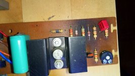
Here are some more photos:
Imgur: The most awesome images on the Internet
Someone has suggested this scorching is normal, and that the problem is possibly on the amplifier boards.
Imgur: The most awesome images on the Internet
Someone has suggested this scorching is normal, and that the problem is possibly on the amplifier boards.
Discolouration of paxolin type boards is a normal reaction to heat.
You need to identify the resistor on the circuit diagram. Is it on the small power supply board or the larger main amplifier board ?
You need to identify the resistor on the circuit diagram. Is it on the small power supply board or the larger main amplifier board ?
Discolouration of paxolin type boards is a normal reaction to heat.
You need to identify the resistor on the circuit diagram. Is it on the small power supply board or the larger main amplifier board ?
Mooly, it's on the power supply side. You can see the board on this link:
Imgur: The most awesome images on the Internet
I'm wondering if the heat is coming from above.
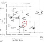
Looking at the circuit in post 13 Tr200 could be driving TR201 too hard because RV200 trimmer resistance is not set correctly.
There is a significant heat sink on TR201 - The hope is there is a good chance it can withstand up to 1W of dissipation.
As someone pointed out this circuit is a shunt regulator which pulls down on the unregulated supply - so an incorrect trimmer setting can increase the dissipation from TR3 causing further heating and a reduction in the regulated supply voltage which should be 67 V.
I suspect you will find a lower voltage than this - you should measure and note what you have.
If not correct as a first step - with the power off I suggest you measure the resistance between board connection point 12 and the base of TR200 - then mark the point on the black part of trimmer body on RV200 in line with the white adjustment slot for reference. (You can stick a little masking tape to the black body and mark the reference with a ballpoint pen.)
TR200 conducts increasingly when the emitter has a more positive voltage on it than at the base - to reduce the conduction in this circuit the base needs to be made more positive which means making the resistance you just measured lower in value.
You can see what direction of rotation you need to take to do this by moving trimmer however far is necessary and return this to the marked original position.
After replacing R206 measure the voltage at connection point 15 to see if the value has changed. If not then gently turn the trimmer in the direction indicated by the experiment mentioned above while monitoring the voltage at connection 15.
You have used a hosting service for your photos
They will soon disappear !!!!!
Pictures -- Why Not attach Them ??
Please use the forums attachment for future photos.
Andy
They will soon disappear !!!!!
Pictures -- Why Not attach Them ??
Please use the forums attachment for future photos.
Andy
Attachments
Seeing as you mention it 🙂 we have a dedicated thread showing how to do this:
How to attach images to your posts.
How to attach images to your posts.
- Home
- Amplifiers
- Solid State
- Quad 303 overheating