Hello, I bought this 120W mono amp from ebay.
Dual DC 32V 2SA1943 2SC5200 120W Mono Channel KSA100 Amplifier Board DIY Kits | eBay
Does not sound to my expectation. Middle and high frequency is not transparent enough. I made ltspice simulation so i would like to try to improve it.
I'm not happy with frequency response 🙁
It's possible to fix somehow ?
REAL measurement:
frequency response
spectrum 1kHz
limitation 1kHz 4ohm
square 1kHz 4ohm
square 10kHz 4ohm
Simulation frequency
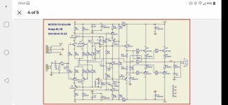
Schematic
Dual DC 32V 2SA1943 2SC5200 120W Mono Channel KSA100 Amplifier Board DIY Kits | eBay
Does not sound to my expectation. Middle and high frequency is not transparent enough. I made ltspice simulation so i would like to try to improve it.
I'm not happy with frequency response 🙁
It's possible to fix somehow ?
REAL measurement:
frequency response
An externally hosted image should be here but it was not working when we last tested it.
spectrum 1kHz
An externally hosted image should be here but it was not working when we last tested it.
limitation 1kHz 4ohm
An externally hosted image should be here but it was not working when we last tested it.
square 1kHz 4ohm
An externally hosted image should be here but it was not working when we last tested it.
square 10kHz 4ohm
An externally hosted image should be here but it was not working when we last tested it.
Simulation frequency
An externally hosted image should be here but it was not working when we last tested it.
Schematic
An externally hosted image should be here but it was not working when we last tested it.
Attachments
Mods
hi Dhaman,
Two years ago I have used several of these units for a multi-amp system.
I concluded that the amps did not live up to their expected performance.
This is what I did:
C6, C7 changed to: 47pF/NPO
C17 changed to : 22pF/NPO
R2 changed to: 27K
C18 changed to: 220uF/50V
Optional: R5, R6, R10, R11 to 100 Ohm
have fun!
Last edited:
the 100W ClassA KSA100 has 2000W (per channel) of output devices.
That amp has 2 pair of 150W devices giving just 600W of output devices.
You cannot hope to clone a KSA100 from that !
That amp has 2 pair of 150W devices giving just 600W of output devices.
You cannot hope to clone a KSA100 from that !
What voltage are your rails?
Have you compared that schematic to the actual KSA100 original or MKII?
You did not include your models file for the .asc, that might help.
Have you compared that schematic to the actual KSA100 original or MKII?
You did not include your models file for the .asc, that might help.
Last edited:
Hi all,
Thank you for your help.
@Piersma: thank you I will try your changes. Simulation looks better now.
@AndrewT: I think this is not Krell KSA100 classA amp. Looks like normal AB amp. Mr JR who design it used wrong name for this amp 🙁
@PB2: Voltage is +-30VDC, I attached the models

Thank you for your help.
@Piersma: thank you I will try your changes. Simulation looks better now.
@AndrewT: I think this is not Krell KSA100 classA amp. Looks like normal AB amp. Mr JR who design it used wrong name for this amp 🙁
@PB2: Voltage is +-30VDC, I attached the models
Attachments
Are you aware of what output power to expect with +/-30V? It is not much by the way.
You should be able to go with +/-45 perhaps 50 unloaded for quite a bit more output
into 4 and 8 ohm loads, would not go to 2 at the higher voltage.
What model are your speakers and their impedance?
You should be able to go with +/-45 perhaps 50 unloaded for quite a bit more output
into 4 and 8 ohm loads, would not go to 2 at the higher voltage.
What model are your speakers and their impedance?
This amp has a lot of degeneration on both the diff pair and the VAS.
So much that there is not enough open loop gain for distortion reduction.
The Cdom caps are far too large.
It clips at 5V less than the rail because of the large VAS degen and the
cascode.
The simulation with 35V rails clips at about 50W out, yours will be much
less with 30V rails. I don't know how they make these amps at such a low
price and I worry about fake transistors. If you believe that they are real
then it should be safe to raise the supply voltage to 40-45V rails. Check
in simulation if any resistor values need to change to keep the bias currents
at a safe point. This will get you closer to 100W out. I would then only
use the amp with 8 ohm loads and be sure to have enough heat sink.
The design is not very good.
Last edited:
Rails
There a most probably chinese counterfeit semi's used on these boards, but none of the six boards I have used failed. I have tested two ofthe boards on 52V rails, the other ones on 42V.
There a most probably chinese counterfeit semi's used on these boards, but none of the six boards I have used failed. I have tested two ofthe boards on 52V rails, the other ones on 42V.
THD
If you feel the need to improve THD figures:
Change R13, R16 to 6.8 kOhm
Change R18, R19 to 150 Ohm
Change R21 to 100kOhm
have fun!
If you feel the need to improve THD figures:
Change R13, R16 to 6.8 kOhm
Change R18, R19 to 150 Ohm
Change R21 to 100kOhm
have fun!
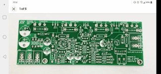
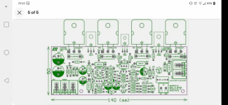
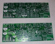
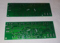
Hello guys.
I bought bare 2 boards from pics attached cuz I have some laying around chips c5198 and a1941 from some car amplifier (vodoo brand 4ch rated "1500w"), so I bought those board in hope that I would be able to build decent stereo amplifier but since I'm pretty noob about electronics I need help.
First is it possible with these boards to make good amplifier ?
Second if it's possible than I would like if someone can tell me which components to use and what to change or what is important to check or test ?
Ps. I would like to connect it on transformer around 300w which has 45-0-45 output on idle up to 50-0-50 .
Thanks.
Attachments
Yes, it is possible to make a good amplifier with this boards and genuine parts. Just follow the advice in this threat.
Do not go beyond 50V rails.
Do not go beyond 50V rails.
I found this pic of parts on some other site and I hope those are parts related for that board ?
Does it matter will resistors be 0.5w or 0.25w if they are same value and same tolerance rating, I mean can I put 0.5w resistor in place where it goes 0.25w resistor?
For genuine parts will be pure luck cuz I have only ebay option and I have bunch of old parts from other amplifiers (not Chinese ones) and other electronics.
Ps. Board still aren't came, so I can't give more information and updates.
Thanks for reply, for sure I will try to follow all advices here cuz I really would like to make a decent amp.
Attachments
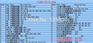
Follow the screenshots from post #15 for parts and placement. 0.25W resistors will be sufficient, 0.5W resistors are also fine.
The KSA100 amplifier was "borrowed" from prof. Leach.
https://www.diyaudio.com/community/threads/professor-leach-amplifier.372482/
https://www.diyaudio.com/community/threads/professor-leach-amplifier.372482/
Finally boards are arrived, and for my eye they are looking okay. Still waiting some resistors and I will heva to get some of those capacitors specially those "wima" for input filter or I will try some others.
Attachments
- Home
- Amplifiers
- Solid State
- Dual DC KSA100 ebay improvement help