I'm trying to figure out what could cause this. I turn the amp on and it takes nearly 2 minutes to come on. Very slowly sound and the VU meter comes up.
Happens only if left off overnight. If turned on after an hour or so it's just fine. It also otherwise works normally.
At first I thought it must be the two big main caps as one was slightly bulged. So I've changed both but it didn't fix the problem.
Fuses are not blowing so there is not excessive load so I can't think of what could it possibly be? It must be somewhere in power supply but apart ftrom the main caps there isn't much there to cause problems. I did check surrounding caps but all are ok too. I'd welcome any ideas, thanks.
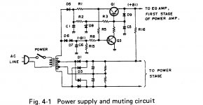
From my experience it will be an electrolytic capacitor, resistor or transistor in the protection circuit that can cause the problem.For eg: The resistor could go high preventing the cap from charging up and turning on the transistor. Im a Sansui guy mainly but a Pioneer Guru should appear here soon to help you out.😀 Here is the muting circuit for Pioneer SA-508 this is where the problem will be. You can get the free service manual from elektrotanya.com,you can get 2 manuals a day or more if you log in. P.S. check D8 to see if its putting out the right voltage as well.
Attachments
Last edited:
Much appreciated, thank you. I just got circuit from HIFI Engine where I'm all ready member but will need to study it while the amp is open so I can make sense out of it. I'm not that great with SS circuits.
But high resistor does make sense, it could cause slow charge. But it takes overnight for the problem to happen so I only have about a minute to test voltages before it's normal again, than I have to wait another day. I wish it would just fail, would be easier. I keep running it whole day and it's otherwise working normally. Even at high levels there is no low power distortion or VU dimming, nothing abnormal.
Edit - I did notice that when I turn it on next day, the amp (speakers) hum for first 20 sec or so before the power gets up to normal. I also noticed that when I turn it on while it's plugged in to my inline mains "light bulb protector", there is no power spike on start as it should be when caps are charging. (Light bulb doesn't monetarily light up).
Last edited:
Change the electrolytic caps in the circuit because thats what the usual culprit is with these symptoms. I suppose you have a Digital Multimeter,if not get one and check the resistors and diodes in that circuit too particuly diode 1 and 3. I dont know what your expertise is with reading reisistors and using a soldering iron but you said you replaced the main filters so thats good. It makes for cracking good bass again,like when the amp was new. Ive marked all the components that could go wrong on the schematic,resistor 2 and 3 are the ones that set the timing for capacitor 5 to mute but you should check them all anyway and any voltages.Check resistor R16 as well? Its a 2watt 15k ohms Good luck mate.
Attachments

Last edited:
That's great, thanks a lot for the help! Yes I replaced the main caps, used higher value since wasn't possible to find the same but at least they have more headroom now. Sounds the same, yes nice solid bass on these amps. I have no problem checking components, soldering etc, I've been building tube amps for years but solid state just eludes me. Tubes make more sense to me (simpler) but SS doesn't, it's a totally different ball game to me. I will be checking the components suggested this weekend.
The amp is starting to fail now, it took nearly 5 minutes to come up to full power this morning, i took a video of it. I am glad because this will give me more time to check the components before it settles down. Hopefully I find it, I like this amp a lot. I'll report back.
The amp is starting to fail now, it took nearly 5 minutes to come up to full power this morning, i took a video of it. I am glad because this will give me more time to check the components before it settles down. Hopefully I find it, I like this amp a lot. I'll report back.
Im the opposite when it comes to Tube amps,schematics and point to point wiring Im hopeless.Ive learnt everything I know on S/S from this site and at AK so I think its only right that I give something back by helping out other people. Youll get this fixed no worries at all. The circuit description for the muteing circuit is on page 6 of the S/M. I had to read it a few times to wrap my head around it. LOL The amp is getting on in years now so it would be best to replace all the electro caps in the power supply while youre at it. I would recommend Panasonic FC and FM as the best caps to use,they are just as good as the supposed ""audio types"" and a lot cheaper. Anyway good luck mate.
I'm glad you've send me the part of schematic where it shows values and PCB. Schematic I have is only bare circuit, too hard for me to follow.
I did some measurements and I have a feeling that the R2 (3.9k) might be bad. It does read 3.9k but maybe under load it develops more resistance. I'll try find one tomorrow and replace it and see. In the pic attached I've marked some voltages I'm getting at full power.
On cold start you can see the SLOW where it goes up really slowly.
If the R2 is ok than there is diode after it but I can't see it causing this problem, I'm not sure but at least couple of things are eliminated and thank goodness trafo is ok. I'll report back again.
An externally hosted image should be here but it was not working when we last tested it.
Last edited:
I could wait so changed the R2 tonight. It's the same so the resistor is ok. I'm not quiet sure what else could be chocking the current. Do you know what is the function of that c1626 transistor that says 34.6V on it? Looks big enough to handle main current, I'm thinking maybe for switching the power on startup so the amp doesn't thump since there is no relay for that? You mentioned muting circuit if that's what it means.
Last edited:
If all the components in the muting circuit read OK with your DMM then all you have to do is replace the electro capacitors. C5 probably isnt holding charge. They need changing anyway. P.S. What is Zener diode D8 reading? If that reads OK its the caps more than likely.
Last edited:
R2, R3, and C5 determine the time Q1 takes to turn on, turning Q1 on is the goal. So if you monitor the voltage on the base of Q1 you'll see it climb until the amp starts to function. If too slow or not at all more than likely C5 is to blame. You can check R2 and R3 but that's not a very stressful part of the circuit. Q3 is part of the turn off circuit.
Craig
Craig
Finally!
I've found 7 cracked solder points so I have re-soldered most of the connections on PCB. It's a wonder it worked normally.
Also checked the R15 and rest of the resistors, all ok. Checked diodes D9, D8, ok too.
Checked C4 and C5 ok, than C5 - that was the one! Was leaky on underside and tested 15% loss.
I used same value but 100V instead of 50V caps. I think it shouldn't make any difference if it's not in audio section. Next time there is a fault I'll recap whole amp. But it's old, there is oxidation on all components legs, fuses, etc so who knows what else might go. I am amazed that none of the connector posts with wires winded on them having resistance issue. I never understood why they didn't solder them in the first place and than there is the so hard to remove glue they used to secure some parts with 🙂
Anyway I'm yet to test the amp over next few days but so far so good and I wanna thank you all for help.
Last edited:
Thats good that you found those cracks,it must have been dropped at some stage. Check to see if the transistors have ""Black Leg"" Its a black oxide coating on the pins that can cause problems,you can take them out and clean them or just replace them. The glue they use,at least on the Sansuis goes dark brown and conductive causing problems like you have, oxidizing resistor and transistor pins. When you do the recap make sure you scrape all that glue off. Its an amplifier worth fixing up to go another 50 years. The 100v cap is OK,no worrys there.
I'm not a fan of wire-wrap either. It is a very good connection as long as it is not disturbed. As part of the winding each corner of the square pin nicks the coating the the wire so there many little connection points on each pin. The bad part is that it is usually solid core wire that easily breaks if moved around a lot during servicing. I think wire-wrap got it's start in main frame computers, there are literally thousands of connections in one of those old main frames. I used to work on Zerox Sigma 5 computers back it the late 70s/early 80s, lllllooooootttttsssss of wires. Yes the glue sucks too.
Craig
Craig
Not dropped, I meant solder cracks in the PCB eyelet where legs are inserted. I find these can happen when the component runs hot and eventually the solder goes dry and cracks. I got this amp some years ego from a guy who just threw it (he said) in an open backyard shed and left it there for years. Humid, hot, cold, you name it. It still worked but the nature oxidated some parts on the inside. The case and chassis were crocked and power trafo mount was bend from the impact..... The face and case surface were great by some mirracle though. I restored all that, and it looks great again. It's a survivor 🙂
Black leg - yes most of the legs do have some stage of oxidation, not all are totally black but not great either. I would have to change everything. I guest if it survived what it did, I better leave alone.
Yes the Wire Trap, strange way to do wiring but does appear to be reliable over time. But I agree the wires can break easy even just by moving them, happened to me few times on other devices so I try not to move them.
And this morning the amp started just fine so all is good I think.
Last edited:
I had symptoms where the SA-508 wouldn't power up immediately and I've now fixed it. The display was blank or dimmed for a few minutes. Eventually the unit faded into operation but there was always a buzzing. These kind of symptoms are pretty much always capacitor related. I assume the unit was made in the early 1980s, so the orignal caps would have been 35 years old!
I found this thread useful so I'm posting my success story:
1) Removed C2/C3 (8000 µF @ 42V)
2) Cleaned PCB both sides
3) Replaced new capacitors in the ready-made alternate holes to match spacing.
http://cpc.farnell.com/vishay/mal205657103e3/capacitor-10000uf-40v/dp/CA05249?st=10000uf 40V
I went for Vishay 85°C 12,000 hour caps rather than the 105°C 5,000 hour ones. The voltage is 2V lower than specced at 40V but the expected voltage on the rails is 32V.
BTW, does anyone have full service manual for this amp, not only schematic? I need full PCB picture, like fragment, published here.
Properly done wirewrap is actually more reliable than soldering as the wire is cold-welded to the gold-plated pins by the high contact pressures a wire-wrap tool applies. A proper joint requires a certain number of turns bare wire and a certain number of turns with insulation on. (something like 6 and 3 IIRC)I'm not a fan of wire-wrap either. It is a very good connection as long as it is not disturbed. As part of the winding each corner of the square pin nicks the coating the the wire so there many little connection points on each pin. The bad part is that it is usually solid core wire that easily breaks if moved around a lot during servicing. I think wire-wrap got it's start in main frame computers, there are literally thousands of connections in one of those old main frames. I used to work on Zerox Sigma 5 computers back it the late 70s/early 80s, lllllooooootttttsssss of wires. Yes the glue sucks too.
Craig
Humans are very variable in their soldering performance, wirewrapping is much more consistent in quality, a big reason for the reliability. Visual inspection is more accurate for wirewrap joint quality too. My suspicion is that its basically impossible to have a bad wirewrap joint pass visual inspection.
Soldering a wirewrap joint opens it up to risks of tin-whisker growth and atmospheric corrosion, reducing long-term reliability.
When I used to do wirewrap I hated it, you have to stare at a mass of sharp pointy things which I found the opposite of relaxing!
Replaced D8 with 1N4003 (was no original Zener to replace), resoldered all PCBs. I think, all that left to be done - is to replace caps. Already working, all DC readings are within normal range, but AC humming is heard. After full restoration i'll use it to drive my headphones collection.
Getting in late....
WireWrap was specifically invented by Bell Telephone for the billions of connections in a national telephone system.
Wire wrap - Wikipedia
When done to Bell Standards, with very specific specifications on pins, wires, and tools, it was very-very reliable.
Quickly adopted into mainframes. *Not* the contemporary IBM 701 which was solder; WireWrap came to IBM in the transistor brains of the later 1950s.
My daddy taught me that the most unreliable part of a mainframe was the solder joints. WireWrap offered speed and proven reliability.
Good enough for the Apollo Guidance Computer.
In either cases, telephone or computer, solder or WireWrap, I do not envy the folks who had to do the work.
The 1953 job used "skinned wire". In the 1960s(?) came a Kynar insulation which would reliably bite-through and also added damping to the wrap.
WireWrap came down into mundane electronics, and not always to Full Bell Spec. Yes, I have seen some "wrap" only good for 90 day warranty, and have soldered it to make the best of a bad situation.
...I think wire-wrap got it's start in main frame computers, there are literally thousands of connections in one of those old main frames....
WireWrap was specifically invented by Bell Telephone for the billions of connections in a national telephone system.
Wire wrap - Wikipedia
When done to Bell Standards, with very specific specifications on pins, wires, and tools, it was very-very reliable.
Quickly adopted into mainframes. *Not* the contemporary IBM 701 which was solder; WireWrap came to IBM in the transistor brains of the later 1950s.
My daddy taught me that the most unreliable part of a mainframe was the solder joints. WireWrap offered speed and proven reliability.
Good enough for the Apollo Guidance Computer.
In either cases, telephone or computer, solder or WireWrap, I do not envy the folks who had to do the work.
The 1953 job used "skinned wire". In the 1960s(?) came a Kynar insulation which would reliably bite-through and also added damping to the wrap.
WireWrap came down into mundane electronics, and not always to Full Bell Spec. Yes, I have seen some "wrap" only good for 90 day warranty, and have soldered it to make the best of a bad situation.
Attachments

- Home
- Amplifiers
- Solid State
- Pioneer SA-508 Very slow start