So far I have repaired and restored several Revox B750 integrated amplifiers and I have always noticed a presence of a background noise. A typical transistor rustle which goes up and down with volume control and changes flavour with tone controls. I believe that the cause lies in extensive use of older transistors, particularly in preamp sections, such as:
BC107
BC140
BC160
BC177
BC179
BC190
BC266
In addition, I believe part of the noise comes from obsolete voltage regulators: 78/79GU1 and 78/79M20.
As I do not have an in-depth knowledge of particular types of transistors, I would like to know if some or all of the listed transistors are known as noisy and would replacing them with more modern equivalents reduce the background rustle. What is your opinion on such "updating" of the amplifier and could you suggest replacement types for these transistors? On the other hand, would there be a downside of such replacements?
Thank you in advance for your replies and advice.
Small signal transistors, as your BC107, BC177, BC179, nowdays are replaced by BC546 to 550 (NPN) and BC556 to 560 (PNP), respectively. Depending on the supply voltages, BC107 possibly can be replaced by the low-noise BC550 and BC177/179 by BC560. Small power transistors as BC140/160 usually don't contribute to the noise floor that much.
Best regards!
Best regards!

While transistors can become noisy and intermittent in old age, it is the exception, not the rule. Something appearing this consistently suggests a problem that lies deeper. Clearly, noisy old voltage regulators could play a role, but it takes subpar inherent PSRR of the circuitry or subpar grounding for that to become a problem.
Looking at the schematic, I can already see that the preamp section has the same kind of pass-me-on grounding that the Sansui AU-5900 from the same time had. Not necessarily a problem as long as you don't try to bypass any power rails to it. (See the last thread on said amp for how this can backfire.) The input board also shows some ground loops, but that could just be the schematic ("ground is ground") and would have to be verified by looking at the actual board.
The input circuitry is mostly followers, these should have decent PSRR.
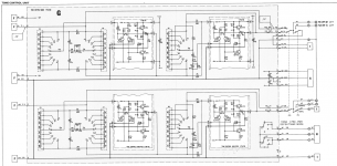
Power setup is complicated by them stacking two sets of +/-20 V rails to obtain +/-40 and +/-20 V (plus +/- 10 V using some unregulated voltages). Capacitance on the regulator outputs is kept to a minimum (a few µF at best), maybe so that they could skimp on protection diodes. The input board uses a pair of cap multipliers with BD139/140 to generate a set of filtered supplies. Unfortunately both sets of supplies are called +/-20 V, so you can't tell which is which - morons. I assume all the input amp circuitry (including phonopre) uses the filtered supplies though.
I would suggest:
1. Obtain some nice, low-noise 78M20/79M20s - a lot of them are, but not all of them (ON Semi or NJR are good, for example). Unfortunately 20 V is a bit of an oddball value. Skip this step if you can't find any.
2. Up output capacitance for all 4 regs significantly - to like 220-470 µF if you can fit those.
3. Add the customary protection diode from output to input (and reversed for the 79xx) - 1N4002 or something. This is just so that the cap from step 2 can discharge upon poweroff without damaging the reg.
4. 78GU1C does not strike me as anything that would still be in production, but you can try the old LM3x7 low-noise trick: Add a small electrolytic (3.3-10 µF) across (R1||R5) and (R3||R6), respectively - observing polarity. A small protection diode (oriented like D3 or D6) should also be added in parallel, 1N4148/1N914 is plenty.
5. On the input board, up the cap multiplier filter capacitors from 10µ to maybe 100-220 µF, space permitting. (MkI: C15/C26, otherwise: C11/C33.) If space is tight, consider going from single RC (2k2/xxµ) to RCRC filtering. I would also experiment with separating filter capacitor return from GL/GR and using the unused 3A terminal (present in the 1st edition) to attach a new wire that runs alongside +/-20 V back to ground on the power supply board. Maybe they had planned to do this originally but the other solution proved "good enough".
I would start with step 5, then 2+3, 1, and 4. And look at grounding on the input board, as mentioned.
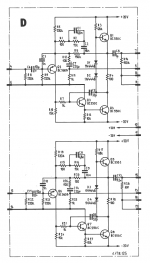
Bonus tweak: A few 10 µF of electrolytic across both of the bias / level shifting diodes D1+D2 / D3+D4 in the phono amp. Should reduce distortion there. BTW, no clue what the R69 adjustment in the 1st edition board is supposed to be good for, it's just a variable load on the output?!
Looking at the schematic, I can already see that the preamp section has the same kind of pass-me-on grounding that the Sansui AU-5900 from the same time had. Not necessarily a problem as long as you don't try to bypass any power rails to it. (See the last thread on said amp for how this can backfire.) The input board also shows some ground loops, but that could just be the schematic ("ground is ground") and would have to be verified by looking at the actual board.
The input circuitry is mostly followers, these should have decent PSRR.
Power setup is complicated by them stacking two sets of +/-20 V rails to obtain +/-40 and +/-20 V (plus +/- 10 V using some unregulated voltages). Capacitance on the regulator outputs is kept to a minimum (a few µF at best), maybe so that they could skimp on protection diodes. The input board uses a pair of cap multipliers with BD139/140 to generate a set of filtered supplies. Unfortunately both sets of supplies are called +/-20 V, so you can't tell which is which - morons. I assume all the input amp circuitry (including phonopre) uses the filtered supplies though.
I would suggest:
1. Obtain some nice, low-noise 78M20/79M20s - a lot of them are, but not all of them (ON Semi or NJR are good, for example). Unfortunately 20 V is a bit of an oddball value. Skip this step if you can't find any.
2. Up output capacitance for all 4 regs significantly - to like 220-470 µF if you can fit those.
3. Add the customary protection diode from output to input (and reversed for the 79xx) - 1N4002 or something. This is just so that the cap from step 2 can discharge upon poweroff without damaging the reg.
4. 78GU1C does not strike me as anything that would still be in production, but you can try the old LM3x7 low-noise trick: Add a small electrolytic (3.3-10 µF) across (R1||R5) and (R3||R6), respectively - observing polarity. A small protection diode (oriented like D3 or D6) should also be added in parallel, 1N4148/1N914 is plenty.
5. On the input board, up the cap multiplier filter capacitors from 10µ to maybe 100-220 µF, space permitting. (MkI: C15/C26, otherwise: C11/C33.) If space is tight, consider going from single RC (2k2/xxµ) to RCRC filtering. I would also experiment with separating filter capacitor return from GL/GR and using the unused 3A terminal (present in the 1st edition) to attach a new wire that runs alongside +/-20 V back to ground on the power supply board. Maybe they had planned to do this originally but the other solution proved "good enough".
I would start with step 5, then 2+3, 1, and 4. And look at grounding on the input board, as mentioned.
Bonus tweak: A few 10 µF of electrolytic across both of the bias / level shifting diodes D1+D2 / D3+D4 in the phono amp. Should reduce distortion there. BTW, no clue what the R69 adjustment in the 1st edition board is supposed to be good for, it's just a variable load on the output?!
Last edited:
Check for the presence of DC voltage at volume pot wiper - even 10mV or so is enough to create that noise.... rustle which goes up and down with volume control...
Furthermore, carbon comp resistors >=100kohms make hiss. I got rid of a lot of hiss in both tube & transistor amps by replacing those with metal film resistors. Under 100k it's hard to hear the difference. I don't think carbon film is as hissy as carbon comp, if your device is newer than 2000.
I'm using 1970 build RCA transistors (input VAS driver) in the right channel of my main (14 hours a day amp). They are pretty quiet. The gas burner pilot light is louder. The channel I built an AX6 driver with On semi 2012 2N5401 input transistor is slightly quieter in hiss, but not much. On quit making TO92 transistors about 2016.
Over here I use On semi MPSA06/56 or MPS8098/8099, have a 20 year stock of both.
I have a 78 GU1C voltage regulator I received as a sample about 1976. There is not any evidence online that fairchild made these things, but I had one, and blew it up. It was very early days for integrated voltage regulators.
Last edited:
It looks like pretty much everything in this amplifier produces hiss: the transistors, the voltage regulators, the ground planes, and - I almost forgot - the carbon composite resistors! OK now, to replace everything would be an obvious overkill. Generally speaking I don't like upgrading or beefing up older equipment, I merely like restoring it as close as possible to its original state. However, in this case, I might try replacing the older transistors and voltage regulators.
The reason I am asking is that, being a Revox fan, I am planning of getting a B700 system as my B system (as the very name suggests it) and was looking for ways to improve the core of the future system, that is, the amplifier.
Thanks everyone for your answers.
The reason I am asking is that, being a Revox fan, I am planning of getting a B700 system as my B system (as the very name suggests it) and was looking for ways to improve the core of the future system, that is, the amplifier.
Thanks everyone for your answers.
It looks like...
Well, no one has actually demonstrated that any of the possibilities is the true cause.
It is quite possible that the amp circuit is simply not very quiet.
Amps of that era often did not use low impedance / low noise input circuits, so the inevitable Johnston noise from resistors is noticeable.
That seems quite likely since you say all of them suffer from the problem.
Need to see the circuit to comment more.
Best wishes
David
Show us the schematic, usually a few transistor uprades and selective resistor upgrades
to metal film should fix it.
to metal film should fix it.
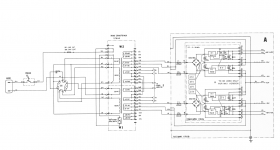
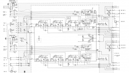
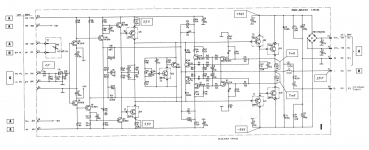
Here are the screenshots of schematics, I hope they are readable.
Attachments

I believe part of the noise comes from..
Belief it's not good enough, you must know..
OK now, to replace everything would be an obvious overkill. .
And end up with sound which you don't like..
Does it have the noise issue on line inputs, tape, aux, tuner or mostly phono only?
Those schematics show BC550/560 in the phono section, is that accurate?
Those schematics show BC550/560 in the phono section, is that accurate?
checking noise while shorting the amp board inputs would be a step in working backwards from the output
(then pitching the rest of the input circuitry, feed the amp board input with modern digital audio source with digital tone/bal/volume, heck even RIAA...)
the amp itself should be OK with ~ 1 Vrms input sensitivity for near clipping output, depending on loudspeakers, listening distance
(then pitching the rest of the input circuitry, feed the amp board input with modern digital audio source with digital tone/bal/volume, heck even RIAA...)
the amp itself should be OK with ~ 1 Vrms input sensitivity for near clipping output, depending on loudspeakers, listening distance
Last edited:
I wouldn't call it an issue, it is rather a higher level of inherent background hiss of this amplifier in general, when compared to more modern equipment. And it is present on all inputs. Of course, as expected, much more on phono input because of high gain, and the hiss there is more of brown noise flavour.
Yes, the BC550/560 are in the phono section. I see little possibility of improvement there because of its simplistic topology and low-noise transistors already used. Besides that, the carbon composite resistors >100k could be replaced.
Yes, the BC550/560 are in the phono section. I see little possibility of improvement there because of its simplistic topology and low-noise transistors already used. Besides that, the carbon composite resistors >100k could be replaced.
Last edited:
Starting with the phono section, you'd want to check the bias points for the first stage to
see if it is optimal from a noise perspective. Replace the first stage collector load resistor
and Q3's emitter load with metal film types. There are certainly lower noise devices than
the 550/560.
I'd recap the electros while in there.
If it is not an issue, then why are you asking for help?
see if it is optimal from a noise perspective. Replace the first stage collector load resistor
and Q3's emitter load with metal film types. There are certainly lower noise devices than
the 550/560.
I'd recap the electros while in there.
If it is not an issue, then why are you asking for help?
On the G, tone control section change the diff pair collector load to metal film, and change
the diff pair transistors to lower noise types - I can't read what's in there and I'm not up
on those vintage transistors.
You probably get the idea, on the F section same thing lower noise first gain stage and the
collector load to metal film. Note that the volume control is at the input to section F.
The C section is upstream of the volume control and they are emitter followers, the emitter
load resistors would go to metal film.
If you hear a change when turning the volume the noise that changes is probably from
those emitter followers, it could also be the change in resistance from the pot loading the
stage input.
Last edited:
I'd recap the electros while in there.
If it is not an issue, then why are you asking for help?
Thanks for your input. I wanted to say that it is not an issue or fault in a particular piece but the general property of this amplifier.
The amplifier has been duly recapped.
You can also select an input, note the noise level, then ground a point at the output
of the follower outputs after the cap so that you don't short DC and note the
reduction in noise. That is the best you will do by improving the circuit upstream
of the ground point.
That is a busy preamp, the Dyna PAT-4 has 4 transistors per channel, including
phono and line with tone controls.
of the follower outputs after the cap so that you don't short DC and note the
reduction in noise. That is the best you will do by improving the circuit upstream
of the ground point.
That is a busy preamp, the Dyna PAT-4 has 4 transistors per channel, including
phono and line with tone controls.
Bipolar electrolytics along the entire signal path.
As I said earlier..
Belief it's not good enough, you must know..
Bipolar capacitors are the worst passive electronic component for audio signal..
- Home
- Amplifiers
- Solid State
- Silencing the noise floor of an older amplifier