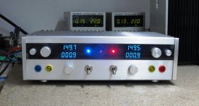
I am not a tube guy. So I do not have a high voltage lab supply lying around on the bench. Only a pair with max. 30V 5A. But recently I want to experiment with a solid state amp for electrostatic headphones. So I thought a lab supply capable of +/- 400V 60mA, regulated, and with adjustable current limit would be handy.
To reduce costs, I want to use my low voltage supplies I already have, and use a switcher to convert it to the required high voltage, low current. After quite a bit of searching on the net, the not-so-obvious LT3751 actually fits the requirements best. The standard circuit on the datasheet is supposed to be capable of 500V 170mA. And all the components, including the transformer, is readily available. Apart from my specific application, I thought this might also be rather useful for tube fanatics not willing to compromise on their choice of Car Hi-Fi gear.
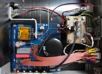
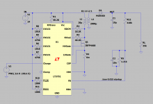
The schematics attached are as built successfully. They largely follow those on pages 26 & 34 of the datasheet. The negative version is not listed on the datasheet. It requires reversing the primary of the transformer, as well as the usual polarity changes after the secondary. Because the built-in “regulator” only accepts positive voltage, the output feedback voltage has to be inverted by an additional inverter using a LT1006.
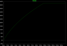
I had quite a bit of trouble getting the converter to start without triggering the voltage limits which then turned the converter off. It could of course be due to the high current draw at start-up, and the current limit of the upstream lab supply. In the end, after a lot of trial and error, I managed to get a stable set up by using a 1k-4.7µF de-bounce at the charge pin. It also helped to lower the supply voltage to 22V. And I also found the inclusion of C6 (10nF) necessary.
To allow a coarse selection of output voltage, the feedback series resistor is split into 8x 49.9k. This, together with a 6-pole rotary switch, gives 6 output voltage steps between 170V and 420V.
Patrick
.
To reduce costs, I want to use my low voltage supplies I already have, and use a switcher to convert it to the required high voltage, low current. After quite a bit of searching on the net, the not-so-obvious LT3751 actually fits the requirements best. The standard circuit on the datasheet is supposed to be capable of 500V 170mA. And all the components, including the transformer, is readily available. Apart from my specific application, I thought this might also be rather useful for tube fanatics not willing to compromise on their choice of Car Hi-Fi gear.
The schematics attached are as built successfully. They largely follow those on pages 26 & 34 of the datasheet. The negative version is not listed on the datasheet. It requires reversing the primary of the transformer, as well as the usual polarity changes after the secondary. Because the built-in “regulator” only accepts positive voltage, the output feedback voltage has to be inverted by an additional inverter using a LT1006.
I had quite a bit of trouble getting the converter to start without triggering the voltage limits which then turned the converter off. It could of course be due to the high current draw at start-up, and the current limit of the upstream lab supply. In the end, after a lot of trial and error, I managed to get a stable set up by using a 1k-4.7µF de-bounce at the charge pin. It also helped to lower the supply voltage to 22V. And I also found the inclusion of C6 (10nF) necessary.
To allow a coarse selection of output voltage, the feedback series resistor is split into 8x 49.9k. This, together with a 6-pole rotary switch, gives 6 output voltage steps between 170V and 420V.
Patrick
.
Attachments

Last edited:
The “regulator” of the LT3751 has a hysteresis of 5%. That amounts to 20V at 400V output. So an additional analogue downstream regulator is unavoidable. Since I also wish to have adjustable current limit, a current-source-fed shunt regulator becomes the natural choice. The current source would need a headroom of at least 10V. So for 400V regulated output, the LT3751 is set to give 420V “regulated”, etc.
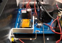
The CCS was made up of 4x IXCP10M90S in parallel, each degenerated to give 50mA, giving a total maximum output current of 200mA. A further set of selectable degeneration resistors allows variable output current of 5mA ~ 200mA. The output voltage is measured with voltage divider R1-R2 and compare to the reference made up of Vbe of Q3 in series with the LM329. Q3 is loaded by another CCS using a LND150, which in turn drives the gate of the shunt device. The dissipation of the shunt device eventually limits the maximum output current, in case of an accidental open-circuit at the output load. As I only require 400V 60mA, the chosen TO220 devices are more than sufficient.
I included a pair of digital voltmeters and ammeters. Both of these require a 5V supply with a Gnd reference to the negative pole of the measurement leads. Hence these 4x 5V supplies have to be all floating. Rather than batteries, I chose to 4x Murata NME0505SC instead. These has isolated outputs from their inputs of minimum 1kV, ideal for the purpose.
Patrick
.
Attachments
Someone asked for PCBs.
There were some mistakes in the PCB which were corrected manually during the build.
As I ever intended to build one, the PCB design was not revised.
I also have no extra boards remaining, even those with mistakes.
So terribly sorry.
The schematics posted are correct.
They also follow those in the datasheet.
So you can just use the datasheet schematics if you want to build one.
Just be careful when choosing components and watch their voltage rating.
Thanks you for your interest,
Patrick
Unlike the designs of the late Jim Williams, the transformers are available directly from Coilcraft: Flyback Transformers for Linear Technology LT3751 | Coilcraft
Someone asked for PCBs.
There were some mistakes in the PCB which were corrected manually during the build.
As I ever intended to build one, the PCB design was not revised.
I also have no extra boards remaining, even those with mistakes.
So terribly sorry.
The schematics posted are correct.
They also follow those in the datasheet.
So you can just use the datasheet schematics if you want to build one.
Just be careful when choosing components and watch their voltage rating.
Thanks you for your interest,
Patrick
1) The LT3751 package (TSSOP or DFN) has a Pin 21 on the underside of the chip which presents an obstacle for using it with a TSSOP-to-DIP adapter to test it out on a breadboard. LT3751 Datasheet and Product Info | Analog Devices Any way to get around this without designing a custom PCB?
2) Have you tried using this supply in an audio amplifier(s)? If so, was it quiet compared to other power supplies you have used?
3) Has anyone been able to simulate this circuit based on the schematic in the first post? If so, can you post the updated file?
Thanks!
- Home
- Amplifiers
- Power Supplies
- LT3751 Driven, +/-400V Shunt Regulated Supply