I am in the process of designing a new phono pre and would like to use the 6c45p tube. I had build a earlier version with R load but after much research have found out that it is not optimal.
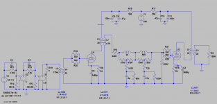
One issue that I want to overcome is the tube ageing which lowers transconductance plate resistance (Rp) rises. So as the tubes age the filter is no-longer being fed from the same impedance and the frequency response will impact the LCR network. To minimize this I want to use the LL1671 with 4:1 step down. I think this will minimize the Zout divination as the tube ages. The overall amp still has 60dB gain so it should be good.
I also plan on using the K&K High Voltage Shunt Regulator Kits to load the transformers. Not in the attached schematic yet.
YOU GUYS ARE EXPERTS PLEASE LET ME KNOW IF THIS IS A GOOD IDEA OR NOT? or how I could improve the design.
THANK YOU
Attachments
The 12dB gain loss due to the transformer is a very substantial hit and will also adversely impact SNR in the following stages. Some sort of follower either a cathode or source follower impedance matched (still some loss) to the LCR network should provide the source impedance consistency you need over time with reasonable SNR and gain compromises.
The LCR network seems to be 8k.
A 4:1 transformer would present the tube with a 128k load impedance which does not make sense at all.
A 600 ohm LCR would work well in this schematic (and probably sound better).
A 4:1 transformer would present the tube with a 128k load impedance which does not make sense at all.
A 600 ohm LCR would work well in this schematic (and probably sound better).
My first D3A based phono stage used a 64 ohm resistor shunted by 2200uF and I had terrible problems with transient induced bursts of distortion on music that did not show up in static sine wave tests. (This problem was pronounced with Nichicon Muse and less so with Black Gates, but still present)
Operating current in that stage was about 20mA.
I had to shunt these caps with much smaller electrolytics and a film cap which seemed to solve the problem. I believe that the internal ESL of the capacitor was sufficient to cause bursts of oscillation on transients, but I am no longer sure of the exact cause.
I ended up using IR LEDs with a Vf of approximately 1.25V which solved the problem, the remaining issue was variation in operating point tube to tube that forced me to select.
I agree with Pieter's comments about the LCR network impedance, unless you have them already I would definitely go with a 600 ohm network or (hint) even lower and drive with a follower.
Note that most of the phono stage threads whether tube or solid state are located in the Analogue Source forum. I think it might do better over there - if you want me to move it just reply to the thread and I will do so.
Interesting project as you might discern from my other comments in this thread.
Interesting project as you might discern from my other comments in this thread.
Yes I am ok with that Kevin. Thanks! New to DIYAUDIO.
The network is 10k but I will probably go with the groups suggestions and experiment with much lower networks, I have read that equalization at lower levels tends to work better.
I could follow the LCR with a step up transformer but thats another component in the chain and more $$.
This is still a initial stage and I am even looking at 801A DHT or other tubes but DHT dont have the gain really. Love my 26 pre.
I am going to play with some more things and post a updated schematic with Run data.
Thanks everyone.
Thanks for the heads up. I currently use a grid bias with the 6c45p and have never had this problem. I might stick with grid bias for next version.
I ended up using IR LEDs with a Vf of approximately 1.25V which solved the problem, the remaining issue was variation in operating point tube to tube that forced me to select.
It is why I invented Gyrator load in the first place. ;-)
It's also worth checking out the intact audio forum, there is a lot of discussion on lcr riaa stages, and many using 6s45pi 🙂
D3a, ec8010, 5843 and 6s45pi need a lot of care to avoid supersonic oscillation.
Best of luck
D3a, ec8010, 5843 and 6s45pi need a lot of care to avoid supersonic oscillation.
Best of luck
One of my concerns about grid bias in the first stage of a phono stage is that sometimes even batteries can be a bit noisy, and I'm not terribly comfortable putting audio through the battery, there are of course ways around that using a could of resistors and a good quality coupling to isolate the battery from audio and bypass the audio around the batteries and series resistors. That all presupposes that a convenient battery voltage is available for the desired operating point - there are ways around that too of course at the expense of some loss of battery life (year or two vs. shelf life)
I've used 4 out of the 5 tubes SJS has listed and all are very effective VHF oscillators if you are not careful.. lol
Lossy ferrite beads may have less noise impact than grid stoppers in very low level situations, but I continue doggedly to use 47 - 220 resistors as stoppers which is fine with MM and most SUT/cartridge combos which have appreciably greater DCR than the stopper and should possibly be the dominant noise source for Johnson noise at least in a good design.
Lossy ferrite beads may have less noise impact than grid stoppers in very low level situations, but I continue doggedly to use 47 - 220 resistors as stoppers which is fine with MM and most SUT/cartridge combos which have appreciably greater DCR than the stopper and should possibly be the dominant noise source for Johnson noise at least in a good design.
alternative schematic idea
I haven't tried ferrite but the 300 ohm per grid connection seems to work great so far. The grid bias is via a low noise power supply. I am even considering trying a SupperTeddy I think its noise level is at -110dB across the 20-20k range.
I will probably experiment with that and a good old Cathode bias to nail down final design.
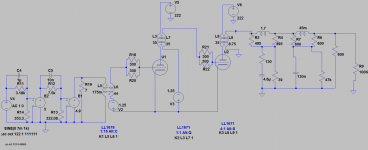
Has anyone experimented with placing the LCR at the tail end of the phono pre?? I came across a few Japanese designs and it looks interesting. It would have no problem driving the 100K pre input Z.
I will still use the 6c45p as the initial to get the gain and maybe wire the OPT 1:4 for even more gain to drive the second tube TBD followed by a step down tranny to drive the LCR.
I attached a preliminary image of the design.
NOTE: This is just the idea, this schematic should NOT be built and does not work!!!!!!!!
I haven't tried ferrite but the 300 ohm per grid connection seems to work great so far. The grid bias is via a low noise power supply. I am even considering trying a SupperTeddy I think its noise level is at -110dB across the 20-20k range.
I will probably experiment with that and a good old Cathode bias to nail down final design.
Has anyone experimented with placing the LCR at the tail end of the phono pre?? I came across a few Japanese designs and it looks interesting. It would have no problem driving the 100K pre input Z.
I will still use the 6c45p as the initial to get the gain and maybe wire the OPT 1:4 for even more gain to drive the second tube TBD followed by a step down tranny to drive the LCR.
I attached a preliminary image of the design.
NOTE: This is just the idea, this schematic should NOT be built and does not work!!!!!!!!
Attachments
I think the concern with placing the LCR in the end of the amplification chain revolves around how linearly the inductors handle the much higher signal levels, another very real concern is the fact that signal amplitudes at 20kHz will be >19dB higher than the levels at 1kHz which could cause high frequency linearity issues in the 2nd stage
Let's say at the input of the first stage (after SUT) you have 5mVrms @ 1kHz, at 20kHz you would have almost 50mV, lets say you have a gain of 40x in that first stage, you now have 2.0Vrms which is more than twice the available bias voltage and the second stage would hard clip, and it wouldn't be very linear at much lower signal levels.
Placing the EQ between stages eliminates this particular concern as the amplitude response at the grid of the second state is now flat. You still have to structure gain such that you achieve the best possible SNR and don't ever drive that second stage into significant non-linearity with any cartridge you are likely to use.
You can address this with careful design and a tube that will accommodate the required operating point for good linearity, it won't be a 6C45P
FWIW I often use dissimilar tubes in one stage vs the other, but I sometimes make exceptions to that rule.
I've used 4 out of the 5 tubes SJS has listed and all are very effective VHF oscillators if you are not careful.. lol
Lossy ferrite beads may have less noise impact than grid stoppers in very low level situations, but I continue doggedly to use 47 - 220 resistors as stoppers which is fine with MM and most SUT/cartridge combos which have appreciably greater DCR than the stopper and should possibly be the dominant noise source for Johnson noise at least in a good design.
I tend to use 2 small lossy ferrites together on the grid and find they sound much better (imho....ymmv) than a resistor whilst also providing the 200 ish ohms required to be effective stoppers at RF
Good tip, do you have a specific recommendation for a ferrite you prefer?
Sorry, no idea where i got them from 😱
They are about 6mm long, about 5mm outer diameter and about 1.5mm inner diameter. I put the grid wire through them with ptfe tube either side to hold them in place. You can probably just about see them on the EC8010 thread. Seems to do the trick.
http://www.diyaudio.com/forums/tubes-valves/302869-ec8010-phono-stage-anybody.html
- Home
- Source & Line
- Analogue Source
- Phono LCR Pre - 6C45P - Transformer