Hi,
As the title says I am selling 6pcbs(3 of each kind).
Both pcbs, the dual and the bipolar are the same dimmensions and have the same mouting holes.
Some details about them
102.54mm * 251.44mm ;
Layers: 2;
PCB Thickness: 1.6mm;
PCB Color: Green;
Surface Finish: Hasl;
Copper Weight: 1;
The boards are designed to be used with avel lindberg 50VA incapsulated transformers.
Transformer input is configured only for 240Vac input.
The dual lt3081 pcb has 2x lt3081 each one connected to a secondary winding of the transformer, completely independent between them.
The bipolar lt3081/lt3091 pcb has one piece of each reg and these are connected each one to a secondary winding of the transformer thus isolated between them also.
I will describe in short what is on the pcbs.
We have ac line in, fuse, transformer primary.Since I have opted for screened transformers I have connected the transformers screen to ac earth as suggested by avel lindberg.
After the transformer I have c rc network to eliminate rectifier diode ringing.I can supply the values of the components for these networks for the 50va 2x20V and 50va 2x12V transformers.
Next are the rectifier diodes, after them a crc filter and finally the lt's.
For the lt's I have included a 1206 smd resistor to setup output voltage, or you can use a pot which has also it's own place on the board.
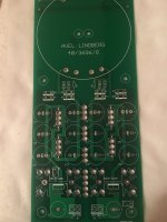
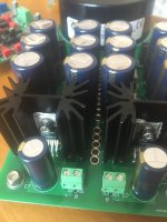
In the first photo you can see the bipolar pcb. If you look on the bottom you will see the outputs which are signed as out_pos and out_neg.
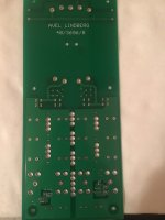
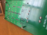
Second photo is the bipolar pcb bottom.
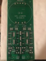
Third photo is the dual ps pcb.
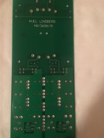
Fourth photo is the dual pcb bottom.
Fifth photo shows the bipolar ps front side.
Sixth photo shows the dual ps powering a b3se dac and cronus reclocker.
Seventh photo show the back of the bipolar ps.
Eighth photo shows bottom of the bipolar ps.
Nineth photo shows the bipolar ps near a legto iv stage which was powering with succes.
All boards are sold
Thanks.
As the title says I am selling 6pcbs(3 of each kind).
Both pcbs, the dual and the bipolar are the same dimmensions and have the same mouting holes.
Some details about them
102.54mm * 251.44mm ;
Layers: 2;
PCB Thickness: 1.6mm;
PCB Color: Green;
Surface Finish: Hasl;
Copper Weight: 1;
The boards are designed to be used with avel lindberg 50VA incapsulated transformers.
Transformer input is configured only for 240Vac input.
The dual lt3081 pcb has 2x lt3081 each one connected to a secondary winding of the transformer, completely independent between them.
The bipolar lt3081/lt3091 pcb has one piece of each reg and these are connected each one to a secondary winding of the transformer thus isolated between them also.
I will describe in short what is on the pcbs.
We have ac line in, fuse, transformer primary.Since I have opted for screened transformers I have connected the transformers screen to ac earth as suggested by avel lindberg.
After the transformer I have c rc network to eliminate rectifier diode ringing.I can supply the values of the components for these networks for the 50va 2x20V and 50va 2x12V transformers.
Next are the rectifier diodes, after them a crc filter and finally the lt's.
For the lt's I have included a 1206 smd resistor to setup output voltage, or you can use a pot which has also it's own place on the board.
In the first photo you can see the bipolar pcb. If you look on the bottom you will see the outputs which are signed as out_pos and out_neg.
Second photo is the bipolar pcb bottom.
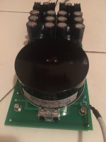
Third photo is the dual ps pcb.
Fourth photo is the dual pcb bottom.
Fifth photo shows the bipolar ps front side.
Sixth photo shows the dual ps powering a b3se dac and cronus reclocker.
Seventh photo show the back of the bipolar ps.
Eighth photo shows bottom of the bipolar ps.
Nineth photo shows the bipolar ps near a legto iv stage which was powering with succes.
All boards are sold
Thanks.
Attachments


Last edited:
Sorry for updating this, I just got so upset about the distance between the heatsinks and those elytics. They will boil away prematurely if the regulators are pushing lotsa juice. This is the perfect example of a very flawed power supply design imho.
Hello, no need at all to be sorry and thanks for your concern.
If you choose properly the transformer’s ac output voltage(aiming for the lowest vdrop on the regs) you will have the regulators barely warm even at 1.5a current draw. In the case you missed the above and chosen a bigger voltage trafo, there is a crc filter onboard that can drop some voltage and this way the heat is spread better on the board. If you still have too much heat you can use an external resistor mounted on a heatsink.
Like I was saying above it all depends on how smart you are when implementing something. If you are less smart you see only the problems if you are a bit smarter instead of seeing the problems you see the solutions.
Thanks again for taking your time to study my design, maybe in the future you will come with something better.
Best regards.
Thanks for the response. I hope you didn't get offended, because that was not my point.
I see these as great chips for simple, high performance DIY variable lab supplies. And in that use, you will get heat. And it is through this mindset I was commenting. That should (in hindsight) been cleared out.
In the DIY scene, good or poor design choices rarely dependends upon intelligence, but knowledge. Thats fortunately something we can get more of, if the dedication is there!
I will post designs for review when ready.
One thing to mention that you maybe didn’t notice, Avel Lindberg produces 5 transformer models that will fit this board. All trafos are 50va with dual secondaries. Voltages range from 9v to 25v.
As these are 50va trafos you will be able to get 1.5a dc only from the 9v transformer(without connecting the secondaries in paralel) so there aren’t many situations when you will be able to draw 1.5a from the power supply. This is one thing, the second thing I didn’t mention nowhere that this is a lab power supply or it can be used as one .
So in one word this power supply is designed to be used with low current devices like dacs, iv stages and preamplifiers. When I draw the boards I had that use in my mind.
If you haven’t already seen the datasheet of lt3081 I recommend you give a look at page 24. They make a nice example of exactly what you search for.
Good luck with your design.
Thanks for the response. I hope you didn't get offended, because that was not my point.
No of course it was not your point to offend. Your point in digging up a 4 year old thread was to strut your superior knowledge in power supply design. If that was not your point then all you had to say was, something along the lines of "be careful there may be some issues with e-cap reliability and the positioning of C3/C6 in relation to the heatsinks". That would've sufficed. Instead, you are so "upset" about this design that another DIY'er provided for others. Did he proclaim to be the best power supply designer ever or maybe he sold these power supply pcb's for 100X his original cost so he made too much profit for such a flawed design in your opinion? No, just this was just a DIY'er trying to help out the community with a few extra boards from a batch he had made selling them for about the same cost as they were to produce. So why are you so upset?
If you wish to design a lab power supply I see no problem with this pcb design. Do you want to know why? Because you do not run a lab power supply with low voltage and high currents 24/7 for months or years on end which is what it would take to boil out a 105C rated cap like the Panasonic FC's he has shown in his pictures. A normal use for a lab supply will have 5V/1A one day, 12V/0.1A the next, 15V/.25A the next, etc. Its a lab supply and most people run various voltages and current draws from one day to the next. I also turn my lab supply off when not in use which is most of the time and I would say most people turn theirs off as well.
If you were really really REALLY concerned about it you could install taller heatsinks, or maybe smaller diameter C3/C6 electro's to allow for more clearance or install a small fan to blow across the heatsinks & e-caps. Or you could set it up to have a smaller adjustment range, say 5V - 15V and use a lower voltage secondary transformer like the OP suggests to minimize the voltage drop. This is a DIY site and sometimes things aren't designed for absolute 30 year lifespan reliability and require a small bit of adaptability from the end builder. However most pcb's are designed to be good quality components and as long as you apply your knowledge in assembling them and use them in the proper manner then they should last for many years. I see a lot of mainstream components that have far worse flaws in them from engineers with supposedly high levels of "knowledge".