I am going to be building a synergy horn for my own amusement. I will be basing my design on Danley's SH64. Instead of asking a few people in PM's I wanted to ask in my own thread. Can someone help me in figuring out how to simulate a synergy horn in HR?
I think once I see how to simulate it I can tweak it from there. I know my mids will work but dont know how they simulate on the horn. Also need to see if I can find a 15 that will simulate well on the horn. I liked the 15NW100 from BC and the 18 Sound 15NLW9300 but they might not work on this horn.
SO hopefully with some guidance I can get started soon on simulations. And then I can start building a few prototypes for the tweeter/midrange drivers. Also wanted to see how much louder the Celestion close back 4" mids will be compared to my Visaton FRS 8M's.
Thanks to anyone who can help.
I have a grasp on the synergy concept from reading the many pages of threads here on DIY, patent and Bwaslo's spreadsheet. SO now its just a matter of figuring out how to simulate the drivers. I walked through the help area in HR but couldnt quite figure out where the taps were being placed and so on.
And thanks RB. The info you attached was a good refresher.
And thanks RB. The info you attached was a good refresher.
Last edited:
If you look at the notes part of my spreadsheet (see link in my sig), and the pdf file that is available for it there are some tips on simulating the midranges on a Synergy horn. The tweeter is just like any other conical horn, the woofers don't really use the horn as anything except a close-to-the-center mounting panel (provided the taps are close enough to keep the reflection nulls out of their passband).
will re-read the pdf again. With four children running around and life being crazy information doesnt always sink in when I want it to.
Do the woofers really matter then on simulation of the horn?
I ask because some drivers work fine in a small ported cabinet but not in a horn. Some drivers works fine in a horn but just need a large horn because of T/S. SO if I am mainly choosing a driver with low Qts and works great in small ported cabinets then that is easier to choose also. Both the BC 15NW100 and 18 Sound 15NLW9300 work. These were also the closest things I could find to the 15HP1020 from Faital pro. So the bass drivers were my main concern. I figured the mids would work fine and so would the CD. But I do like having something to look at simulation wise for expectations.
PLUS I wanted to compare the 3.3" drivers to the closed back 4" Celestions. Then see what I will be missing. The best thing about the Celestions was the fact that they are closed back. Makes things much easier. I like easier.😀
I walked through the help area in HR but couldnt quite figure out where the taps were being placed and so on.
Attachments
Another question:
Is S2 the cross sectional area of the tap and L12 being the distance from the throat?
I think thats how it looks after looking at Bill's spreadsheet again. So S2 is the area for the drivers throat entry. So S2 for the mids will be a smaller number that the woofers.
My other question is how do I figure out the driver front volume again?
Does HR start off with a default 12" driver or does it already start with a simulate driver based on Sd?
And can I only simulate the front chamber on horn? And not back chamber and front together in response?
David in your picture does the S3 driver tap have a shorter length than L23?
I only figured it must because the horn expands at a different rate when going from S3 to S4. So the port could be anywhere on the L23 axis but not after according to the picture.
Sorry if this is confusing I am just trying to understand this so have a grasp of what to enter. First one is always the hardest then after that I should be good. I hope. lol
Last edited:
I'll take the easy questions.
Is S2 the cross sectional area of the tap and L12 being the distance from the throat?
YES on both. Lxy is measured on the axis, not along the horn wall.
Of course S2 is for the mids and S3 is for the woofers
My other question is how do I figure out the driver front volume again?
- there is a wizard in HR to help you estimate but most accurate way if you have the driver is to fill the cone with something and then pour it off into a measuring cup
Does HR start off with a default 12" driver or does it already start with a simulate driver based on Sd?
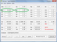
- You enter the driver TS parameters on the "input parameters" screen
A "mid" has both front and rear chambers. Their volumes are entered in the Vtc and Vrc boxes respectively on the input params screen. Same for woofer. Before David added the multiple entry horn wizard, you would simulate mid and woofer separately. I don't know how that works with both in the same simulation. Either you active one or the other or you define a crossover (which would be too much to ask)
Is S2 the cross sectional area of the tap and L12 being the distance from the throat?
YES on both. Lxy is measured on the axis, not along the horn wall.
Of course S2 is for the mids and S3 is for the woofers
My other question is how do I figure out the driver front volume again?
- there is a wizard in HR to help you estimate but most accurate way if you have the driver is to fill the cone with something and then pour it off into a measuring cup
Does HR start off with a default 12" driver or does it already start with a simulate driver based on Sd?
- You enter the driver TS parameters on the "input parameters" screen
A "mid" has both front and rear chambers. Their volumes are entered in the Vtc and Vrc boxes respectively on the input params screen. Same for woofer. Before David added the multiple entry horn wizard, you would simulate mid and woofer separately. I don't know how that works with both in the same simulation. Either you active one or the other or you define a crossover (which would be too much to ask)
Thanks. I understood his drawing in meaning S3 was the woofers but in the drawing the point of tap for the woofers was before S3. SO thats where I was confused. Just guessing but it looked like the pictured showed a different length for the than where S3 looks like it is in the picture. The dotted line is S3 and then flares out to S4 in a length of 20cm.
SO maybe thats where the ME1 and ME2 record come into play. I will look at wizard and see if I can get the schematic to look like David's for my own "design."
Front volume question from me was because when I look at the wizard it show a diameter of 320mm I think. So, I am simulating 15's and the diameter would be bigger than that. So thats where I thought maybe it started off with a 12" by default.
I dont have a 15" driver yet. I am trying to see if either of my three choices will work.
w/o the driver, just guesstimate using the wizard in HR. Its not that critical for the woofer as you aren't trying for extended HF response. Nevertheless, include the volume of air in the hole through the horn wall in your Vtc
David in your picture does the S3 driver tap have a shorter length than L23?
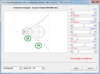
The schematic diagram shows a horn system with four segments.
The high-frequency driver is located at the horn throat. The cross-sectional area at that point is S1.
The mid-frequency drivers are located at an axial distance L12 from the horn throat. The cross-sectional area at that point is S2.
The low-frequency drivers are located at an axial distance L12 + L23 from the horn throat. The cross-sectional area at that point is S3.
I only figured it must because the horn expands at a different rate when going from S3 to S4. So the port could be anywhere on the L23 axis but not after according to the picture.
The expansion rate changes at S4, not S3. The ports for the low-frequency drivers are at S3. The first conical 'part' of the system is made up of 3 segments, with the areas S2 and S3 chosen to give an overall consistent flare rate (the rates do not necessarily have to be the same, it just so happens that they are in the design example I used). It is necessary to use 3 segments to enable the positions of the mid and low frequency drivers to be specified.
The second conical 'part' of the system is made up of 1 segment, specified by S4, S5 and L45.
The interfaces between the 4 segments are shown as dotted lines - coloured red at the driver positions, and grey elsewhere.
Nevertheless, include the volume of air in the hole through the horn wall in your Vtc
Just to clarify, the volume of air in the holes through the horn wall should be accounted for using Ap1 and Lp, not Vtc.
Attachments
Before David added the multiple entry horn wizard, you would simulate mid and woofer separately. I don't know how that works with both in the same simulation. Either you active one or the other or you define a crossover (which would be too much to ask)
The Multiple Entry Horn Loudspeaker Wizard tool has options enabling low, mid, and high frequency responses to be shown either individually or combined, with or without active filtering.
The thing to keep in mind is that, unless your horn is quite huge or if the mids don't go very low, it isn't really being much of a horn for the woofers. So in most cases you can just calculate what 1/4 wavelength is at the mid-to-woofer crossover point and make sure that your woofer taps are at least about 20% closer to the throat than that. You basically have a box with a reflection point recessed into it. If you are going for the whole enchilada (i.e., a tapped horn within the Synergy horn for bass) then you have more work to do, but I don't have much (at least not successful) experience with that one.
If your horn is big enough to be a horn at the woofer frequencies, though, then you do have to model it the same as you would a midrange regarding tap points, port lengths and areas, front volumes, etc. (I've always modeled them as separate using same tap at a different S2, never tried doing the woofer along with the mids, that way is new to me)
If your horn is big enough to be a horn at the woofer frequencies, though, then you do have to model it the same as you would a midrange regarding tap points, port lengths and areas, front volumes, etc. (I've always modeled them as separate using same tap at a different S2, never tried doing the woofer along with the mids, that way is new to me)
Last edited:
Thanks David and Bill.
It is very slowly starting to make sense. I will try and post an attempt and see what I did wrong. I also dont know how to simulate a compression driver because most companies dont have any T/S parameters. I can simulate a 4552 from BMS only because someone else has done it before. But I dont think I could enter Cms properly?
Cms=140E-06m/N I dont think it would let me put 140 in at all.
And Bill I dont think I could build a horn large enough to horn load the 15's.(meaning I dont have the room) Would love to try and build a J3 in the future but I will start with the SH64 for now. Then I can tackle a paraline.
And Bill since my horn is 34" wide it looks like the horizontal coverage is only down to 360hz. Not sure how much this will help the 15's but thats why I am trying to simulate them.
I will be using either the 3.3" FRS 8M from Visaton or the 4" Celestions. SO I think the mids will go down low enough just fine to cross to the 15's. As I said I am loosely copying the SH64. I already have the Visatons but see now that I can order the Celestions. And CD's I have a couple that I could use. 1.4" and 1.5".
The Multiple Entry Horn Loudspeaker Wizard tool has options enabling low, mid, and high frequency responses to be shown either individually or combined, with or without active filtering.
AWESOME!
I'll have to take time to learn it though my first Synergy just got to the critical listening stage.
Cms=140E-06m/N I dont think it would let me put 140 in at all.
Enter 140E-06 as 1.40E-04.
- Status
- Not open for further replies.
- Home
- Loudspeakers
- Multi-Way
- Can someone help me simulate a Synergy Horn