Hi all:
I seem to be stumped with what I thought would be a simple task to correct the high DC offset in the L channel of this amplifier (408mV).
In addition, I can't seem to diagnose the reason for the high voltages in the low voltage power supply. The R201/R202 values of 221/3.92K should give 24V and not 29V. Both the regulators (LM337 & LM317) are getting fairly hot, so there is obviously a problem somewhere.
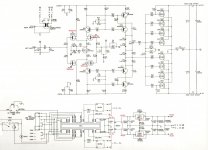
I've attached the schematic with my measured voltages in red. What am I missing 😕 ?
Rgds
Mayank
PS: History of work I've done so far on this amplifier:
1. The original 20,000 uf/75V electrolytic capacitors for the High Voltage power supply were leaking. These were replaced with 31,200uF/80V. I realize this may be a bit on the higher side, but they were the only ones I could source to fit within the height restriction.
2. Low voltage power supply was +26.3V/-35.8V instead of +/- 24V. Suspected LM337 to be faulty. Replaced both regulators. Voltage now is +29.0V/-29.2V.
3. DC offset: 2.4mV [R channel] but 408mV [L channel]. Presumed the input differential transistors may have drifted out of spec with age, replaced Q1 & Q2 and Q3 & Q4 with matched pairs of 2SK163/2SJ44. No change in DC offset
I seem to be stumped with what I thought would be a simple task to correct the high DC offset in the L channel of this amplifier (408mV).
In addition, I can't seem to diagnose the reason for the high voltages in the low voltage power supply. The R201/R202 values of 221/3.92K should give 24V and not 29V. Both the regulators (LM337 & LM317) are getting fairly hot, so there is obviously a problem somewhere.
I've attached the schematic with my measured voltages in red. What am I missing 😕 ?
Rgds
Mayank
PS: History of work I've done so far on this amplifier:
1. The original 20,000 uf/75V electrolytic capacitors for the High Voltage power supply were leaking. These were replaced with 31,200uF/80V. I realize this may be a bit on the higher side, but they were the only ones I could source to fit within the height restriction.
2. Low voltage power supply was +26.3V/-35.8V instead of +/- 24V. Suspected LM337 to be faulty. Replaced both regulators. Voltage now is +29.0V/-29.2V.
3. DC offset: 2.4mV [R channel] but 408mV [L channel]. Presumed the input differential transistors may have drifted out of spec with age, replaced Q1 & Q2 and Q3 & Q4 with matched pairs of 2SK163/2SJ44. No change in DC offset
Attachments
Last edited:
Sorry - not an "Expert" with this amp. First thing to do is check your meter. Low batteries usually give higher than actual voltage measurements. SImple test would be a new alkaline battery - should be around 1.6 volts.
I would have started with the input transistors, which you did. Look for open or out of spec resistors. Especially the low value ones (100 and 47.5)
Regulators running warm are not that uncommon, but.... Good luck with it.
I would have started with the input transistors, which you did. Look for open or out of spec resistors. Especially the low value ones (100 and 47.5)
Regulators running warm are not that uncommon, but.... Good luck with it.
I seem to be stumped with what I thought would be a simple task to correct the high DC offset
in the L channel of this amplifier (408mV).
Replace C9 in the nfb loop, it may be leaking. Use a bipolar type.
Low voltage power supply was +26.3V/-35.8V instead of +/- 24V. Suspected LM337 to be faulty.
Replaced both regulators. Voltage now is +29.0V/-29.2V.
The regulators each depend on two precision resistors to set the output voltage.
Replace those resistors, 221 Ohms and 3.92k.
If you're getting a weird voltage out of a 3-terminal regulator, be sure that it's not oscillating. And that at least some of the load connects between + and GND to assure proper start up.
Getting hotter than they should be is also a symptom of regulators oscillating. The danger of course is them taking out other components.
Getting hotter than they should be is also a symptom of regulators oscillating. The danger of course is them taking out other components.
hmmm ...
i'd hope to get the power supply fixed first.
1st of all, i don't have the specs for the lm317/337 memorized.
lm317/337 reference is not super tight tolerance, but I think if the resistors are close (you did measure them to check the values, right?) to spec, you really should see around +/- 24vdc.
i don't recall the max input for the lm317/337 series.
maybe 40v? but that might be 40v max between input and output. might be helpful to make sure, especially if you say they're hot
the real question is where on earth did you get matched 2sk163/2sj44 jfets? and do you still have your right arm?
🙂 🙂 🙂
mlloyd1
hmmm ...
the real question is where on earth did you get matched 2sk163/2sj44 jfets? and do you still have your right arm?
mlloyd1
I was wondering the same thing myself. They were hard enough to get when that amp was in production in the late 80's-early 90's, and in fact later vintages used some different JFETS. And even those alternate p/n's were hard to get without waiting a very long time for a very slow boat.
I wish I could be of assistance in troubleshooting your amp. I'm the one who drew that schematic, but that was a long, long time ago and my skills have since developed severe oxidation.
Last edited:
Both the regulators (LM337 & LM317) are getting fairly hot
You should probably also replace the input and output electrolytic capacitors on the regulators, in case those are bad and oscillating.
You should probably also replace the input and output electrolytic capacitors on the regulators, in case those are bad and oscillating.
oscillating electrolyt's ?? Thats a new one !
Q1 and Q2 has to be matched, the same goes for Q3 and Q4.
If they are not, the output sends back a voltage to correct the difference.That results in an output offset.
Mona
If they are not, the output sends back a voltage to correct the difference.That results in an output offset.
Mona
oscillating electrolyt's ?? Thats a new one !
A bad electro could cause the 337 to get stupid. They are known to be finicky with respect to the combination of load and capacitance. The unstable regions can be different depending on brand. And be worse on some 2nd source (or even fake) devices.
Don't take things as facts ...Some things need to be verified again and again
On ground connector that is rusty or loose might bring the secondary PSU out of balance ,check that is critical , One scratchy mono stereo switch could also do problems ( is messing up with the feedback )
Kind regards
Sakis
On ground connector that is rusty or loose might bring the secondary PSU out of balance ,check that is critical , One scratchy mono stereo switch could also do problems ( is messing up with the feedback )
Kind regards
Sakis
Not sure if you've fixed this yet. The high voltage on the regulated rails sounds like they are running unloaded. Check Q8, 9, 10, & 11. These transistors are running extemely hot and are prone to failure. They are easy to spot as they generally have dark spots on the pcb around them where the pcb has discolored due to the heat. Generally they start to cause crackling and popping noises when they go but yours may have just opened completely.
I replaced mine with the 1 watt versions, MPSW56 & 06.
I replaced mine with the 1 watt versions, MPSW56 & 06.
Regret the delay in getting back to you all - I was stationed in remote/rural Tanzania where access to internet is still a challenge.
I am pleased to report that my Hafler 9300 power amplifier has been restored to its former glory and that it has (permanently?) taken the place of my Aragon 4004-II in our main living room set up. It really sounds awesome. Thank you all for your words of wisdom and suggestions.
I am listing the various issues identified & resolved. Hopefully these may help someone else working on similar units:
[a] Main power supply:
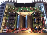
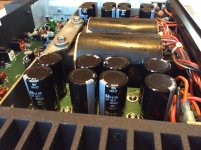
Of the 4 15,000uF/75V (schematic had these as 20,000uF) main PSU capacitors, one was short and 2 were leaking. As the rail voltage is +/- 77V the 75V capacitors had been working beyond their rated voltage. Sourcing modern 2" height replacements to fit in the narrow space is virtually impossible. I replaced each with 4 3,900uF 80V capacitors in parallel mounted on a "daughter" board which was bolted to the original screw terminal holes on the PCB. 16 capacitors in all with the higher 80V rating. Several DIY members have asked about these, so I will post pictures below for reference.
Low voltage PSU:
This was completely rebuilt. I suspected LM337 & LM317 to be faulty and replaced with new ones from Mouser. The precision 221 & 3.92K resistors were replaced along with the electrolytic capacitors. Diodes checked. The voltages were now back in spec at +/- 24.3V with the LM337/LM317 warm to touch.
[c] Input differential pairs:
I believe to avoid production delays the hard to get input differential FETs may have been substituted on the production floor which caused a problem in my unit once the low voltage supply increased to -35.8V with the faulty LM337.
The correct complement of 2SK163 is 2SJ44 and not 2SJ74 which were installed in my amplifier. 2SK163/2SJ44 are 40V devices while 2SJ74 is the lower 25V device. I replaced the SK163/2SJ74 with matched pairs of 2SK163/2SJ44.
[d] High DC offset/No bias:
The design (and the amplifier) had MPSA06/MPSA56 transistor pairs which were operating very hot. Extremely hot. As a result, the copper tracks on the double sided PCB had hair line burn cracks due to the heat. These were carefully repaired and the MPSA06/MPSA56 replaced with their 1W MPSW06/MPSW56 siblings. Offset was now at a respectable level at 0.3mV and 0.8mV.
[e] Electrolytic Capacitors:
All electrolytic capacitors in the audio path were replaced with Nichicon Gold/Muse. The capacitors in the power supply were replaced with HE 105 long life/low impedance.
[f] Bias:
The manual stated the bias to be set at 260mA. I decided to go with a lower 210mA setting to further reduce the chance of the MPSW06/MPSW56 overheating.
[g] Typos in the Manual & Schematic:
Transistors Q6 & Q7 are MPS6521/MPS6523 and not 2N6521/2N6523 as marked on the schematic and parts list.
Well worth the investment - the amplifier really sounds wonderful. I am listening to one of my favorite CDs - Alchemy (Dire Straits) as I write this. It never sounded so clear and musical!
Rgds
Mayank
Answering specific queries/comments:
From our very own Vendor's Bazaar. Great pricing and fast shipping - do search for 2SJ44.
Wow. Honored to make your acquaintance Sir! Yes indeed - difficulty in sourcing components may have led to the incorrect substitution of 2SJ44 with the lower voltage 2SJ74 device.
Sakis you were spot on! I initially did not think necessary to verify that the copper tracks on *both* sides of the PCB near the very hot running transistors MPSA06/MPSA56 could be the problem. They were!
Appreciate the recommendation - the overheating was the reason for failure/break in copper tracks. The amplifier is running much cooler with the new 1W MPSW06/MPSW56 and lower bias.
I am pleased to report that my Hafler 9300 power amplifier has been restored to its former glory and that it has (permanently?) taken the place of my Aragon 4004-II in our main living room set up. It really sounds awesome. Thank you all for your words of wisdom and suggestions.
I am listing the various issues identified & resolved. Hopefully these may help someone else working on similar units:
[a] Main power supply:
Of the 4 15,000uF/75V (schematic had these as 20,000uF) main PSU capacitors, one was short and 2 were leaking. As the rail voltage is +/- 77V the 75V capacitors had been working beyond their rated voltage. Sourcing modern 2" height replacements to fit in the narrow space is virtually impossible. I replaced each with 4 3,900uF 80V capacitors in parallel mounted on a "daughter" board which was bolted to the original screw terminal holes on the PCB. 16 capacitors in all with the higher 80V rating. Several DIY members have asked about these, so I will post pictures below for reference.
Low voltage PSU:
This was completely rebuilt. I suspected LM337 & LM317 to be faulty and replaced with new ones from Mouser. The precision 221 & 3.92K resistors were replaced along with the electrolytic capacitors. Diodes checked. The voltages were now back in spec at +/- 24.3V with the LM337/LM317 warm to touch.
[c] Input differential pairs:
I believe to avoid production delays the hard to get input differential FETs may have been substituted on the production floor which caused a problem in my unit once the low voltage supply increased to -35.8V with the faulty LM337.
The correct complement of 2SK163 is 2SJ44 and not 2SJ74 which were installed in my amplifier. 2SK163/2SJ44 are 40V devices while 2SJ74 is the lower 25V device. I replaced the SK163/2SJ74 with matched pairs of 2SK163/2SJ44.
[d] High DC offset/No bias:
The design (and the amplifier) had MPSA06/MPSA56 transistor pairs which were operating very hot. Extremely hot. As a result, the copper tracks on the double sided PCB had hair line burn cracks due to the heat. These were carefully repaired and the MPSA06/MPSA56 replaced with their 1W MPSW06/MPSW56 siblings. Offset was now at a respectable level at 0.3mV and 0.8mV.
[e] Electrolytic Capacitors:
All electrolytic capacitors in the audio path were replaced with Nichicon Gold/Muse. The capacitors in the power supply were replaced with HE 105 long life/low impedance.
[f] Bias:
The manual stated the bias to be set at 260mA. I decided to go with a lower 210mA setting to further reduce the chance of the MPSW06/MPSW56 overheating.
[g] Typos in the Manual & Schematic:
Transistors Q6 & Q7 are MPS6521/MPS6523 and not 2N6521/2N6523 as marked on the schematic and parts list.
Well worth the investment - the amplifier really sounds wonderful. I am listening to one of my favorite CDs - Alchemy (Dire Straits) as I write this. It never sounded so clear and musical!
Rgds
Mayank
Answering specific queries/comments:
the real question is where on earth did you get matched 2sk163/2sj44 jfets? and do you still have your right arm?
mlloyd1
From our very own Vendor's Bazaar. Great pricing and fast shipping - do search for 2SJ44.
I was wondering the same thing myself. They were hard enough to get when that amp was in production in the late 80's-early 90's, and in fact later vintages used some different JFETS. And even those alternate p/n's were hard to get without waiting a very long time for a very slow boat.
I wish I could be of assistance in troubleshooting your amp. I'm the one who drew that schematic, but that was a long, long time ago and my skills have since developed severe oxidation.
Wow. Honored to make your acquaintance Sir! Yes indeed - difficulty in sourcing components may have led to the incorrect substitution of 2SJ44 with the lower voltage 2SJ74 device.
Don't take things as facts ...Some things need to be verified again and again
Sakis you were spot on! I initially did not think necessary to verify that the copper tracks on *both* sides of the PCB near the very hot running transistors MPSA06/MPSA56 could be the problem. They were!
These transistors are running extremely hot and are prone to failure. They are easy to spot as they generally have dark spots on the PCB around them where the PCB has discolored due to the heat. Generally they start to cause crackling and popping noises when they go but yours may have just opened completely.
I replaced mine with the 1 watt versions, MPSW56 & 06.
Appreciate the recommendation - the overheating was the reason for failure/break in copper tracks. The amplifier is running much cooler with the new 1W MPSW06/MPSW56 and lower bias.
Mayank,
Thanks for the follow-up. Its always nice to have a resolution to an issue. Too many times people ask for help and do a lot of work on troubleshooting their gear on the forum only to disappear with no resolution.
Thanks for the follow-up. Its always nice to have a resolution to an issue. Too many times people ask for help and do a lot of work on troubleshooting their gear on the forum only to disappear with no resolution.
indeed.
i'm embarrassed to admit i'm just now seeing the followup myself, years later.
mlloyd1
i'm embarrassed to admit i'm just now seeing the followup myself, years later.
mlloyd1
Mayank,
Thanks for the follow-up. Its always nice to have a resolution to an issue. Too many times people ask for help and do a lot of work on troubleshooting their gear on the forum only to disappear with no resolution.
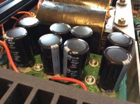
Pictures of the new 4 x 4 3,900uF/80V PSU capacitors in place on a "daughter" board.
This is a great solution. I've heard several reports of the 9300's big brother, the 9500, having bad main filter caps. Those are impossible to replace, since the originals were custom made for the application, and I haven't been able to find anything with the correct electrical value in a size that will fit.
So this is a very viable solution for keeping the 9300 and 9500 (and their variations) alive. Great work!
Trans Nova 9300
Mayank I am having the identical problems of popping. After finding your post I decided to check my voltages . The +70 to both channels is fine. The +24 is fine but the -24 is -32.1. So i need to replace the LM337 regulator. I was able to decrease or temp relieve the popping by using freeze spray. It is the second day and the amp is working fine but it's only matter of time before it comes back with vengeance.
I was wondering if you would be able to provide a copy of the user manual with the schematics, parts location and parts list. There appears to be several sites that have schematics and even manuals for the 9500 the larger sibling but even those have the schematic and parts location and parts list wiped clean. It would be a great help to those of us shooting bugs in the dark so to speak. Like after my parts replace I'd like to check the bias. so the bias setting instructions would be useful.
Thanks in advance.
I am pleased to report that my Hafler 9300 power amplifier has been restored to its former glory and that it has (permanently?) taken the place of my Aragon 4004-II in our main living room set up. <snip>
Mayank I am having the identical problems of popping. After finding your post I decided to check my voltages . The +70 to both channels is fine. The +24 is fine but the -24 is -32.1. So i need to replace the LM337 regulator. I was able to decrease or temp relieve the popping by using freeze spray. It is the second day and the amp is working fine but it's only matter of time before it comes back with vengeance.
I was wondering if you would be able to provide a copy of the user manual with the schematics, parts location and parts list. There appears to be several sites that have schematics and even manuals for the 9500 the larger sibling but even those have the schematic and parts location and parts list wiped clean. It would be a great help to those of us shooting bugs in the dark so to speak. Like after my parts replace I'd like to check the bias. so the bias setting instructions would be useful.
Thanks in advance.
I also think it's great solution. Mother of invention and all that. I guess one of the mysteries surrounding the 9300 other than a schematic there doesn't appear to be anything else. I have one of these and just noted on the capacitor replacement pics that my -24V regulator is positioned 90 deg from Mayank's. No biggy but starts you wondering. My -24 reg needs replacement it is reading -32V. I was able to relive the popping by freezing the general area of the MPSa06/56 area. I don't think the cans of freeon are still available this is an old tv repair tool. I still had some. Thought Id give it try .

- Home
- Amplifiers
- Solid State
- Hafler Transnova 9300: DC offset & power supply puzzle