I'd first like to say that this is a GREAT forum! I have learned much just reading about, so thank you all.
Now, on to the project at hand. I have an unmolested Classe Thirty that needs attention. I am pretty happy with it overall, but it was their entry level offering. Fortunately, there are remarkable similarities between the Classe' pre's of that period (Thirty, CP-30, CP-35, CP-40, etc). When coupled with the technological advancements since 1992, I am confident much can be gained within the existing platform. That said, here is the list of potential areas of interest.
1. Power supply: -Capacitors (4x Nichicon VX 1000uf/63v, 2x Phillips HP 3300uf/25v) I did notice the CP-35 had 4700uf caps. -Regulators (L7815CV, 7805A and MC7915C).
2. Phono stage: There are a few electrolytic's which could easily be replaced with Nichicon KZ and ES for NP's.
3. General opamp: This thing is packed full of OP27's and it seems those should be the first to go. I am planning to put adapters so they can be swapped more easily.
That is where I am at the moment. I know there are opamp discussions all over this forum, but never having actually changed one, I felt an inquiry within reason. I would prefer to find direct replacements if at all possible. I would also like to avoid major design modifications as this just my way of familiarizing myself with the components in preparation for a full-on DIY pre. Idea's?
Attachments
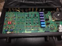
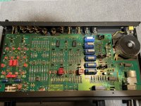
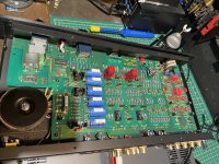
Boy, that's a very '80s board layout. All neat and tidy, not necessarily good.
XLR jack hookup looks suspect. Pin 1, like connector shield, should go directly to case (which in turn ought to connect to star ground somewhere else), not signal ground. Pin 1 is always the cable shield.
Looks like the outputs circuitry uses a discrete output stage for better current driving capabilities, seems to be a very basic affair with all resistors though (no bias diodes). Lack of heatsinking points to lowish currents (transistors are Philips BD139/140 or similar, I guess?), so probably heavily emitter degenerated. One would have to draw out the schematic.
More later.
That's good. I forgot that Classé belongs to this group.
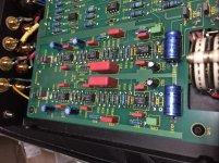
I'm spotting a number of things already. (All component numbers for left channel, add 100 for right.) I can tell you one thing right away, this thing isn't even close to state of the art for 1992.
Goofs:
* Aside from the pin 1 problem (on ins and outs), balanced input topology is basically OK but resistor values are wacky (please check in real life). A poor little TL072 used as a buffer is asked to drive, worst-case, 1 kOhm (R119). The OP27 used as a bal/unbal converter would also break a bit of a sweat. R119-122 values could all be increased by a factor of 10. R123, by contrast, could be reduced by the same amount. I would prefer R115/117 to be more like 220-330 ohms, 1% MF or better.
* The tape out buffer which could use some output series resistors doesn't have any. TL072s have been known to appreciate up to 470 ohms.
* Both of the above circuits have 511 ohm series resistors in the supply rails, probably for protection reasons. Why, then, you would not include supply bypass caps for the opamps is beyond me. When Yamaha does something like that they might be using 220 ohms and 100 µF or thereabouts. Sure you have to take care where to ground them so you don't introduce power supply crap into your audio ground (usually taken care of by dedicated power ground), but anyway. A little 100n between supplies would have been the least you could do.
* If resistor values were too low on the input side, the output stage has them too high, making it unnecessarily noisy. R130/131 should be scaled down a factor of 10-15. BTW, a gain of 20 dB seems a bit high, too, though I have no idea what sort of input sensitivity the corresponding power amps would have had. For a more standard gain of 16 dB and change, you could use 1K5 and 8K2.
Tweaks:
* The MC prepre is hardly the lowest-noise thing ever. I'd suggest replacing IC101 by an LT1128 and scaling down R101, 104 by almost a factor of 10 (49R9 and 499R should be fine).
* IC103 in the phono preamp sees very high impedance imbalance and should be a type with low current noise and low input impedance distortion. I'd try an OPA1641 using an SOIC adapter. BTW, it's interesting that they went for a passive RIAA as popular in DIY circles.
I'll sim the output buffer and see whether that can be improved, too.
Last edited:
...Yup.
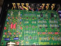
1. Replace R133, 135, 141, 143 by 1N4148 or 1N4001 diodes observing polarity (R133/141: ring towards opamp output, R135/143: ring towards Q102/104 base). Ups output stage current to a few mA at least, brings down distortion pre-feedback by more than 6 dB.
2. Replace R132, 137, 140, 145 by 15 kOhm. As-is, the buffer puts a far greater load on the opamp output than a typical power amp input, which is silly and will only generate unneeded distortion in the opamp output stage.
3. Solder a smallish electrolytic capacitor, maybe 10-100 µF, across the two diodes, i.e. between transistor bases, again observing polarity (- mark like ring on diode).
With all 3, buffer distortion pre-feedback goes from 0.033% to 0.005% when driving 20 Vpp of 10 kHz into 10 kOhm || 10 nF, and buffer input impedance increases from about 1.2 kOhms to a more friendly 7.5 kOhms.
Last edited:
Actually I have an even better idea still:
1. Replace lower resistors R134, 143 by both diodes in series, again observing polarity. Short upper resistors R133, 141.
2. Remove R132, 140.
3. Replace R137, 145 by 10k. (*)
4. Solder a smallish electrolytic capacitor, maybe 10-100 µF, across the two diodes, i.e. between transistor bases, again observing polarity (- mark like ring on diode).
This brings up buffer input impedance to 10k and even provides some Class A bias for the opamp output stage, at the cost of some minor asymmetry / reduced headroom which is not a big deal here.
*) Actually the best replacement for R137/145 in step 3 is a CRD (current regulator diode) or discrete current source. Maybe 5 mA. Then buffer input impedance should go through the roof and there's a healthy Class A bias for the opamp output stage. We can easily afford the extra current draw since we previously reduced resistor bias current by about the same amount.
(Whether it makes sense to run the opamp output stage hotter than the buffer is up for debate, but anyway.)
With 3 diodes or a red LED you'd turn the buffer into a little hottie of about 25 mA idle current that could even drive headphones, but then I'd recommend a bit of a heatsink for the transistors and I'm not sure whether the power supply would be up for it.
Note that I bolded "observing polarity" since not doing so may release the magic smoke.
Last edited:
@ungie Thanks for the schematic! I have been to BW support site and somehow missed it.
@sgrossklass You've given me exactly what I was looking for, thanks! The technology within the Thirty did seem primitive from what I could tell. Though, I must admit: the neat and tidy layout is what made this preamp such an enticing place to start. I have read over the lot of your recommendations and I really appreciate your clarification. I will compile a parts list for each section to be modified. I intend to complete the mod's one section at a time noting improvements along the way. I do have a few question's, but perhaps after disassembling the unit in order to apply xlr pin 1 to the chassis ground, things might make a bit more sense. Again, I greatly appreciate the guidance. 🙂
@sgrossklass You've given me exactly what I was looking for, thanks! The technology within the Thirty did seem primitive from what I could tell. Though, I must admit: the neat and tidy layout is what made this preamp such an enticing place to start. I have read over the lot of your recommendations and I really appreciate your clarification. I will compile a parts list for each section to be modified. I intend to complete the mod's one section at a time noting improvements along the way. I do have a few question's, but perhaps after disassembling the unit in order to apply xlr pin 1 to the chassis ground, things might make a bit more sense. Again, I greatly appreciate the guidance. 🙂
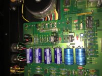
Do you guys think the following could be a suitable relay replacement for whats on there? I think I might have a relay problem.
https://www.digikey.com/en/products/detail/panasonic-electric-works/TXD2-L-5V/649903?s=N4IgTCBcDaICoA0AiYC0AZVBWAaqgckiALoC+QA
https://www.digikey.com/en/products/detail/panasonic-electric-works/TXD2-L-5V/649903?s=N4IgTCBcDaICoA0AiYC0AZVBWAaqgckiALoC+QA
Attachments
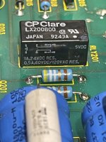
So I seem to have this situation where the preamp trips the protection circuit in my power amp. Any thoughts on what this could be? I measured the voltage on the outputs, they measure up to 12mV, although on the left side a 0 reading after the relay, which leads me to the relay - but anything else might cause this? As soon as the switch it flipped from standby to signal (on) protection circuit goes! I did some basic measurements on the transistors, seemed ok.
- Home
- Source & Line
- Analog Line Level
- Classe Thirty Upgrades?