Hello all -
I just posted all the design details of the LR phono reamp that I designed for ETF.13 on my website: LR Phono Preamp
The preamp (as you might guess) doesn't use any capacitors in the RIAA EQ section, just inductors and resistors. Gain is provided by opamps.
I don't want to get into a debate about why one would want to do this - I'm no capacitor-phobe myself. But for whatever reason, those of us that have built it think it sounds very good indeed!
If you're interested in the topology, make sure you look over the powerpoint presentation that describes the design process.
Pete
Beautiful construction and a very thorough presentation. I clicked thru it and will read in more detail later. You worked very hard to make the EQ work with inductors.........
Hi, not a capacitor phobe either, but I thought that the circuit could be simplified and made less expensive with a couple tweaks.
The reactive components of the cartridge change the phase relationship entering the first gain stage. This will change with every combination of cartridge and loading capacitance. Thus, the impedance exiting the first gain stage is complex.
To simplify the math, (and granted that there is a small penalty to be paid) moving the 75uS pole to the non-inverting input of the first opamp by choosing a load resistor with a value equal to the inductance of the cartridge at 2122Hz.
The LRPP used a single inductor and two resistors to achieve the 3180uS pole and 318uS zero. Here's how I modified the design for a single inductor:
Attachments
Are you worried about crosstalk between the inductors for the two channels? Have you tried grounding one of the inputs and seeing if there are is any induced signal at the output?
-b
-b
It looks like a project I would like to do. I notice that the boards are not yet up on your ebay site. When do you think they might become available?
Thanks
Thanks
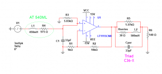
Another possible approach - the concept was lifted from an article in 2003 AudioXpress. The original author used opamps with the L-R network in the feedback.
Another Wrench In the Works... Inductive RIAA
The concept could also be implemented using a hybrid vacuum tube stage with p-channel mosfet output.
Another Wrench In the Works... Inductive RIAA
The concept could also be implemented using a hybrid vacuum tube stage with p-channel mosfet output.
I agree with Conrad in his comment (on the thread you cite) -- inductance is really non-linear. Fortunately Mbe tomorrow I will post some screen-shots different inductors with the VNA
I just built one of these and have a question. I know there are a couple trimmers that are used to set offset to 0VDC at the output with no input. Does this indicate the input should be shorted to ground or just left open. If I zero with input shorted to ground, then I get a couple volts offset with nothing connected to inputs.
- Home
- Source & Line
- Analogue Source
- Posted LR Phono Preamp design