http://w3.uniroma1.it/chemo/image/hifi/st40-sche12-a3.png
I am only getting 12.5 watts out of each channel (10Vrms into 8 ohm resistive load), I tried replacing the cathode bypass caps for the 7591's and that didn't help. I got 405 on the plates and 360 on the screens, bias 14v at cathode and current draw all look fine.
This thing has old 7591 tubes, probably original. I tested them on my Hickok 539b and they test a little below min mutual transconductance. BUT I read here: 7591A tube comparisons That I shouldn't trust the Hickok for gm testing 7591's.
I don't want to fork over the dough for new tubes if I don't have to. I am thinking the low gm is causing the lack of power because the voltage is there and everything else looks fine, but that article has me reluctant to just buy new tubes. I am thinking somebody out there could think of other things to test. One thing is that all the capacitors are original on this unit. The orange wire from the output transformers are going to the 8 ohm tap.
Any thoughts are welcome please.
-bird
I am only getting 12.5 watts out of each channel (10Vrms into 8 ohm resistive load), I tried replacing the cathode bypass caps for the 7591's and that didn't help. I got 405 on the plates and 360 on the screens, bias 14v at cathode
Also check the power supply voltage supplying the 7247 input/phase splitter. If that's low, the output grids won't be properly driven. The R41 could have increased in value. Or, see if the phase splitter clips before the output stage.
Also check the power supply voltage supplying the 7247 input/phase splitter. If that's low, the output grids won't be properly driven.
The R41 could have increased in value. Or, see if the phase splitter clips before the output stage.
Hello rayma, I was using the chassis for common in first measurments and then I thought about it and hooked the ground up to the common on speaker connector, I now get the correct voltage out. I did check R41 and it was a tad high at 10k I replaced it with the correct size and it did help too. I am now measuring 24 watts per channel.
I will hook it up tomorrow and see how it sounds🙂

Bumping old thread as I just picked up an ST40 to restore/re-build and ended up here from search and the correct answer isn't here (or isn't explicit from post 3). A ST40 built to the construction manual would have the yellow 4 ohm tap grounded, not the black common which would explain the incorrect output voltage measured from the chassis.


If the "4" Ohm Tap is grounded, then that means: one output tube cathode connects to the "16" Ohm Tap . . .
and the other output tube cathode ties to the "0" Ohm Tap.
The signal voltage from "4" to "0" Taps, is identical to the signal voltage from "4" to "16" Ohm Taps (but is out of phase with each other).
Connect your speakers: 0 to 4; 0 to 8; or 0 to 16 as appropriate.
Your scope can only measure 4 to 0 or 16 to 0.
Do Not "Float" your scope. Measure 4 to 0 on channel 1, and measure 4 to 16 on channel 2.
Notice the opposite phase. If you scope has the correct functions, 1. Do a Math Add function, and 2. Invert the phase of one channel (menu functions). If there is no menu function 'Invert' , the Math Add trace will show 0 Volts.
Unless your scope has a cycle rms function, you have to measure the peak to peak volts and divide by 2.828.
No scope? Use your DMM or VOM to measure from "0" to "8" into an 8 Ohm load resistor.
You have to get a schematic to prove whether the above statement is true statement or not true . . .
If true, you have re-discovered output tubes cathodes negative feedback.
And that kind of circuit requires "floating" speaker wires.
For safety reasons, the "4 Ohm" tap is grounded, so no DC can arc from the primary to the secondary.
And, for the cathodes to have a DC return, the "4" Ohm tap has to be grounded.
Happy Restoring!
Happy Listening!
Schematic anyone?
If nobody wants to see it, I do!
Last edited:
Actually that is not the case. The ST40 doesn't use cathode feedback through the output winding (I've heard that is an Audio Research patent - not sure). It's a simple cathode biased output stage with 4,8, 16 out and feedback from the 16 ohm tap. The construction manual and schematic are available online with some searching. Why they chose to ground the 4 ohm tap is a mystery to me.If the "4" Ohm Tap is grounded, then that means: one output tube cathode connects to the "16" Ohm Tap . . .
and the other output tube cathode ties to the "0" Ohm Tap.
The grounded 4 Ohm taps allows the connection of a center channel speaker from the "0" terminal on one channel to the "16" terminal on the other. Delivers the sum of left plus right; due to the low output impedance, there isn't much loss of channel separation. Was popular for a few years; Scott, Fisher, Pilot and others used this connection too.
Partial cathode coupling is not an ARC patent (nor a Bill Johnson patent, who used it at Electronic IndustriesActually that is not the case. The ST40 doesn't use cathode feedback through the output winding (I've heard that is an Audio Research patent - not sure). It's a simple cathode biased output stage with 4,8, 16 out and feedback from the 16 ohm tap. The construction manual and schematic are available online with some searching. Why they chose to ground the 4 ohm tap is a mystery to me.
prior to forming Audio Research Corp.). The 4 ohm tap must be grounded to use it, which also makes
push pull nfb available from the 16R and 0R taps.
This Eico does not have partial cathode coupling, though. There is an optional center channel connection,
which uses the grounded 4R tap. Center channel was a big thing for a while at the time, and could be
included for a low mfr cost.
Last edited:
Glad to know the real facts on the ST40.
Thanks!
Back then, there were several methods to modify the 2 channel stereo signal.
Earlier than the ST40, there was the stereo amplifiers that used a push pull output transformer and a single ended output transformer.
The single ended output transformer primary was connected between B+ and the push pull primary center tap.
Then the two transformers secondaries were connected in a matrix that gave the L and R signals out.
Then along several 4 channel stereo methods:
1. 4 Track reel to reel, play the tape one way only (do not fast rewind, flip the tape, turn the sound down, and rewind at the play speed. A fast rewind would destroy the tape, because of the unevenly packed tape, changes in humidity, temperature over time destroyed the tape).
2. Multiplexed LPs with the Shibata stylus that worked all the way to the 50kHz subcarrier, and a decoder box.
3. CBS SQ matrix method, with specially recorded LPs, and amplifier matrix decoder.
4. The Hafler matrix method, with specially recorded LPs, with L-R sent to the 2 rear speakers that were connected in series. I have some of these LPs, and this is the only 4 channel I have listened to in my home.
Then there was the SACD recordings and players. The true 3 channel used RCA's original 3 track recordings, with real center channel microphone and separate channel. Most other modern recording SACDs are "fake", there is no real center channel to the more modern recordings that call themselves SACDs.
Last edited:
Yeah, crazy stuff, and most of them are inferior to regular stereo.
Whoever thought that LPs and turntables could handle 50kHz reliably must have been smoking something.
Whoever thought that LPs and turntables could handle 50kHz reliably must have been smoking something.
Lots and lots of switches in this amplifier.Schematic anyone?
If nobody wants to see it, I do!
Attachments
Last edited:
Rayma,
Thanks for posting the Eico ST40 schematic!
The Fisher 500C / 800C power amp section was similar.
Fisher used a single 12AX7 for the driver and phase splitter; Eico used the 12DW7 'combo' 12AX7 and 12AU7 there.
Fisher used fixed bias. If I remember correctly, the fixed bias voltage was shared by both 7591 tubes.
Eico used a shared self bias resistor.
Both the Eico and the Fisher circuits use bias voltages that are equal for the output tubes . . .
That requires very good matching of the 7591 tubes.
(Primary DC balance is very important for most push pull circuits, for most push pull output transformer models).
Primary DC balance is paramount.
Proof: The graph that relates primary DC balance versus low frequency performance is on the very last page of the Heathkit W-5M manual.
The graph results were taken with global negative feedback connected. Global negative feedback does not fix un-balanced DC, it makes it worse.
(check it out).
I write the above comments, particularly for newbies who may not know about these factors.
Just my opinions.
You can definitely hear a lack of DC balance in the output stage on push pull tube amplifiers.
I don't see the graph in the manual though.
I don't see the graph in the manual though.
Attachments
Last edited:
rayma,
Link:
http://www.mcmlv.org/Archive/HiFi/HeathkitW5M.pdf
The graph is on page 32, just above the yellow section.
It takes a bit of calculation, using and interpreting the graph and the output tubes cathode circuit, in order to see . . .
How very little un-balanced DC causes harmonic distortion of low frequencies.
The schematic is on page 2.
looking at the cathode resistors, and calculating the graph differential voltage versus distortion, you can calculate the low current that causes the distortion.
Hey Summer,If the "4" Ohm Tap is grounded, then that means: one output tube cathode connects to the "16" Ohm Tap . . .
and the other output tube cathode ties to the "0" Ohm Tap.
The signal voltage from "4" to "0" Taps, is identical to the signal voltage from "4" to "16" Ohm Taps (but is out of phase with each other).
Connect your speakers: 0 to 4; 0 to 8; or 0 to 16 as appropriate.
Your scope can only measure 4 to 0 or 16 to 0.
Do Not "Float" your scope. Measure 4 to 0 on channel 1, and measure 4 to 16 on channel 2.
Notice the opposite phase. If you scope has the correct functions, 1. Do a Math Add function, and 2. Invert the phase of one channel (menu functions). If there is no menu function 'Invert' , the Math Add trace will show 0 Volts.
Unless your scope has a cycle rms function, you have to measure the peak to peak volts and divide by 2.828.
No scope? Use your DMM or VOM to measure from "0" to "8" into an 8 Ohm load resistor.
You have to get a schematic to prove whether the above statement is true statement or not true . . .
If true, you have re-discovered output tubes cathodes negative feedback.
And that kind of circuit requires "floating" speaker wires.
For safety reasons, the "4 Ohm" tap is grounded, so no DC can arc from the primary to the secondary.
And, for the cathodes to have a DC return, the "4" Ohm tap has to be grounded.
Happy Restoring!
Happy Listening!
Schematic anyone?
If nobody wants to see it, I do!
Are you saying the 4 ohm tap being grounded is correct?
thanks,
Kelly
I am so glad that old threads are still helping people.
And my thanks to the moderators and providers of diyAudio.
And my thanks to the moderators and providers of diyAudio.
Do both channels deliver the same low level of power output?I am only getting 12.5 watts out of each channel (10Vrms into 8 ohm resistive load), I tried replacing the cathode bypass caps for the 7591's and that didn't help. I got 405 on the plates and 360 on the screens, bias 14v at cathode and current draw all look fine.
Perhaps check the B+ voltage with power being delivered to the load.
If the rectifier is weak then B+ may droop when power is being delivered to the load and so limit output power.
My money is on weak 7591 tubes but checking the rectifier first will not hurt.
A number of years ago I had a heath AA-100 that needed new 7591 output tubes.
I replaced the old 7591 with a new set of matched JJ 7591 tubes.
The results were pretty disappointing.
With real NOS 7591 the AA-100 produced a solid 25 watts of power.
With the JJ 7591 tubes output power dropped to only about 13 watts with higher distortion.
This was a few years ago so hopefully JJ has corrected this issue with current 7591 they make. I can not say as I moved on.
In the end I designed a new AA-100 output board to accept 5881 by redesigning the driver section to provide a higher bias voltage, increased gain and a larger grid swing voltage required by 5881s.
It was a lot of changes but worth it getting me back to factory specifications for power and distortion with the 5881 proving pretty bullet proof.
Last edited:
Just for my own interest I took one of the JJ 7591 I purchased some time ago and ran it trough my uTracer3 and my AVO mark III Characteristic Meter.
The results were interesting and clearly showed why the JJ 7591 tube produced only about 1/2 the output power as NOS 7591 tubes did in a Heath AA-100 amplifier.
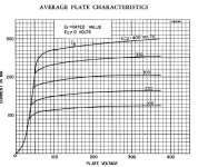
First the AVO results for the JJ 7591
With... Va=Vs=300V, Vg1=-10V as per the Sylvania data sheet page 1.
Measured Result...
gm = 8.5mA/V vs the data sheet of 10.2mA/V
The JJ is a bit low but not alarmingly so.
Ia =40mA vs the data sheet of 60mA
The JJ anode current is much lower at only 2/3 the data sheet anode current.
This will result in lower bias current in many 7591 amplifier designs that have auto or non adjustable fixed bias and so increased distortion.
Although not perfect neither of the above values convinced to me the JJ-7591 was a no go for NOS 7591 replacements in vintage amplifiers and did not explain the poor results I had had with these tubes in a Heath AA-100.
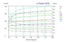
Then I put a JJ-7591 in my uTracer to measure what really defines the maximum power a tube can deliver into a load.
That is the peak anode current vs screen voltage with Vg1 set at zero volts.
Here the JJ-7591 totally fails to deliver the anode current levels specified on the data sheet.
Conside one example.
With Va=70V, Vg2=400V, Vg1=0V...
Looking at the attached curve trace of a JJ-7591 with Va=70v (typically about clipping in a amplifier) you will see the anode current is ~Ia=165mA
The data sheet shows that anode current should be ~ Ia=260mA under the above conditions.
This will result in a power loss of 260/165 or at least a ratio of 1.57. So the 25 watt amplifier become a 15 watt amplifier.
Not far off what I observed in actuall power loss in use in a AA-100.
How much of a loss in performance/power the shortfall in the JJ7591 tube will cause in any one amplifier design will depend on the transformer impedance used, screen voltage chosen and to a degree the anode voltage in the design.
If the design lightly loads the 7591s the power loss may be quite small however if the design runs the 7591 hard (like a AA-100) then the loss in performance will be severe.
I certainly hope that JJ was able to work on their production quality of the JJ-7591 since I purchased these tubes some years ago as there was clearly a opportunity for improvement.
The results were interesting and clearly showed why the JJ 7591 tube produced only about 1/2 the output power as NOS 7591 tubes did in a Heath AA-100 amplifier.
First the AVO results for the JJ 7591
With... Va=Vs=300V, Vg1=-10V as per the Sylvania data sheet page 1.
Measured Result...
gm = 8.5mA/V vs the data sheet of 10.2mA/V
The JJ is a bit low but not alarmingly so.
Ia =40mA vs the data sheet of 60mA
The JJ anode current is much lower at only 2/3 the data sheet anode current.
This will result in lower bias current in many 7591 amplifier designs that have auto or non adjustable fixed bias and so increased distortion.
Although not perfect neither of the above values convinced to me the JJ-7591 was a no go for NOS 7591 replacements in vintage amplifiers and did not explain the poor results I had had with these tubes in a Heath AA-100.
Then I put a JJ-7591 in my uTracer to measure what really defines the maximum power a tube can deliver into a load.
That is the peak anode current vs screen voltage with Vg1 set at zero volts.
Here the JJ-7591 totally fails to deliver the anode current levels specified on the data sheet.
Conside one example.
With Va=70V, Vg2=400V, Vg1=0V...
Looking at the attached curve trace of a JJ-7591 with Va=70v (typically about clipping in a amplifier) you will see the anode current is ~Ia=165mA
The data sheet shows that anode current should be ~ Ia=260mA under the above conditions.
This will result in a power loss of 260/165 or at least a ratio of 1.57. So the 25 watt amplifier become a 15 watt amplifier.
Not far off what I observed in actuall power loss in use in a AA-100.
How much of a loss in performance/power the shortfall in the JJ7591 tube will cause in any one amplifier design will depend on the transformer impedance used, screen voltage chosen and to a degree the anode voltage in the design.
If the design lightly loads the 7591s the power loss may be quite small however if the design runs the 7591 hard (like a AA-100) then the loss in performance will be severe.
I certainly hope that JJ was able to work on their production quality of the JJ-7591 since I purchased these tubes some years ago as there was clearly a opportunity for improvement.
Attachments
- Home
- Amplifiers
- Tubes / Valves
- Eico ST40