I'm fixing up an old car with my daughter- a 1989 Volvo 780. It was fancy back in the day, and had 2 amps, one for the front and one for the back (along with a very awesome looking graphic equalizer).
Everything works fine except for the rear amp. I removed it, and on first inspection noticed a burn mark. I desolder the remnants of a D600 transistor, order a replacement (KSC2690AY, close as I could find), and stuck it in. I also find some cold solder joints on one the large caps, and resoldered them. All the other components seem to be visually ok.
Hooking it all back up, the "remote-on" light- which is the only light on the thing - lights up dim with 12v hooked up and car off. Remote on is sending voltage, but there is no change. Makes no noise or anything.
I have some very dusty electronics experience - I used to repair arcade games - mostly just replacing components-, and I still do a a lot of stuff with microprocessors, so I know my way around a multimeter and soldering iron. This low level troubleshooting is a completely new thing for me, but I'm prepared. On top of it the amp design is strange, with all the connectors crammed into one side.
Where should I start? Thanks!
-rj
Last edited:
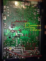
post a pic we will tell you where to do the measurements, there is few data online for those vintage oem amps.
Sure thing!


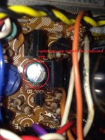
The burned transistor was under the test lead in the last picture-
Not a lot of room in there with all the wires- hope the picture is good enough....
Thank you all!
-rj
The burned transistor was under the test lead in the last picture-
Not a lot of room in there with all the wires- hope the picture is good enough....
Thank you all!
-rj
first basic procedure need to re-solder many components, try to clean pcb with alcohol or any other solvent in order to remove old rosin deposits, let it dry, then power up the unit and check suggested voltages, values are approx not exact.
replace the visible damaged parts like pop up capacitors. report values , will try to answer asap.
replace the visible damaged parts like pop up capacitors. report values , will try to answer asap.
Attachments
Last edited:
That's a good first question- do the caps look sketchy to you guys? They are domed a bit, but not crazy. Easy enough to just replace them tho-
Board is shockingly filthy with rosin- I've gone though 1/4 can of contact cleaner already. I'll get it cleaned up and everything reseated and report back.
Thank you all for your help!
-rj
-rj
Board is shockingly filthy with rosin- I've gone though 1/4 can of contact cleaner already. I'll get it cleaned up and everything reseated and report back.
Thank you all for your help!
-rj
-rj
is better got them replaced coming from 1989 don't expect to work like charm after 25 years. btw must of those could be dry or have low performance.
All good advice so far.
Once you have repaired the burnt board and the bulging cap you need to start by finding out where the problem lies.
Is it a problem with the remote start or is it a problem with the amp ?
Monitor the collectors of the output transistors as you apply a remote ON signal.
Once you have repaired the burnt board and the bulging cap you need to start by finding out where the problem lies.
Is it a problem with the remote start or is it a problem with the amp ?
Monitor the collectors of the output transistors as you apply a remote ON signal.
Great advice- caps are on their way. I'll report back once I have them installed.
BTW, the damaged part of the board is where the transistor blew up. The traces were lifted, so I bridged the components with solder. Not pretty but effective.
-rj
BTW, the damaged part of the board is where the transistor blew up. The traces were lifted, so I bridged the components with solder. Not pretty but effective.
-rj
Update-
Replaced the bulging 100uf cap near the replaced transitor, along with the 3 large caps. The one on the top of the picture looked pretty bad, but the other 2 seemed fine.
Hooking it back up, and I notice that the "remote-on" light is on all the time. Remote power will make the light go dim. I'm not sure of the behavior of this amp, but that seems backwards to me.
There is no sound, click, hum, anything from the speakers. Checking voltages, and I get nothing at any of the points (well,~ .13 v from the 25v tap in the middle of the board.
What is odd is I did not get ground at the rectangular trace to the left of the 25v trace.
It seems as if it isn't turning on at all....
ok. sorry for late response, we need to focus on basic,step by step, oscillation circuitry first : UPC1042C ... - Datasheet Search Engine Download
power up the amp , on uPC1042c post the voltage measurement, with tester's negative lead on power supply negative ground ( not suggested gnd on PCB )
pin1____________ pin16________
pin2____________ pin15________
pin3____________ pin14________
pin4____________ pin13________
pin5____________ pin12________
pin6____________ pin11________
pin7____________ pin10________
pin8____________ pin9________
Alrighty!
With the amp hooked up in car, negative test lead jumpered to chassis ground lead, I got the following:
pin1 - .386 pin16- .68
pin2 - .001 pin15 - 2.95
pin3 - .386 pin14 - .001
pin4 - .113 pin13 - 2.03
pin5 - .001 pin12 - 2.03
pin6 - .002 pin11 - 1.26
pin7 - 1.096 pin10 - .495
pin8 - 0 pin9 - .1
I'm going to hazard a guess and assume that's not the way it should be....
-rj
Very nice. Seems like we have no power on this one. Pin 15 must have 12v when power up. Look the datasheet. Now have to find out where is the lost of power.
This is going to sound stupid, so please forgive me. What normally happens when remote power is applied? Transistor switches unit on? I've usually looked at complex circuits as collections of simple circuits, but I'm having a hard time getting my head around this one. It's so.....condensed? Efficient?
Thanks for everything-
-rj
Thanks for everything-
-rj
Usually it happens that way. Remote pass tru npn transistor the emitter us to be on positive supply. In this amp i don't think would be so hard to follow the track. Just be patient.
I'm tracking down the remote start voltage now. In the end, it's going to end up in that transistor that blew up.
I couldn't really make out the numbers on the charred remains - the only clue is that the 1 or 2 characters I could see matched some of the other transistors on the board. Could I have it wrong? Does a D600 make sense there? It is a NPN transistor.....
Pin 15 goes right to the emitter of that replaced transistor.

One other suspect is a resistor that bridges the base and emitter on the blown up transistor. Its charred to the point the I can't read the colors, but seems fine other than the soot, and looks structurally ok. It's showing 3.2k ohms resistance. That sound right?
Only for test purposes. Feed the pin 15 with 12v try to use 1 amp fuse between power source and pin 15. If the emitter goes to this one it must be some kind of amperage amplifier. But we need to know if everything is fine after this transistor.
Spent a few hours this evening banging my head against the amp.
Pin 15 gets ~ 5 now, after replacing a 100 ohm resistor that seemed questionable. Without remote power, pin 15 gets 7. The base and emitter of that suspected power transistor - the one I changed - are both 5, and the collector is getting the full ~12v.
Jumping 12v to pin15 makes the light up front brighter, and nothing else. No click, no hum, no sound, no effect.
While disconnecting, I noticed something else odd. I always assumed I had a dirty fader pot on the stereo itself, as changing it seemed to effect tone to the front speakers more than volume (turned all to the back removed all treble from the front speakers, and moving it to the front made them normal and bright).
I unplugged the harness that gives input signal and remote power, and the radio volume dropped dramatically. I plugged it back in and verified that the rear speakers were still as silent as ever. I eventually figured out that with the input signals disconnected from the amp, the front fader control works perfect.
I know the amp is probably not even worth the time I've put in already, but I'm feeling stubborn.
- Home
- General Interest
- Car Audio
- Revive old Volvo (Alpine) HA-5161 amp