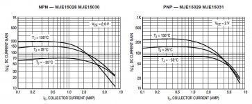
I have been looking at the MJE15028/30/32 and MJE15029/31/33 transistors from ON Semi. The datasheets clearly show a hfe of 150 at 25C stable up to 1A, then falling as we approach the 8A limit. This for both NPN and PNP ; actually the charts are shown side by side.
From that I would determine that I am guaranteed hfe=150 if I keep it below 1A and over 25C.
So I have bought around 3 dozen pairs of those transistors, and I measured them at home. Many I measured at 1A, others at a very small Ic (but the differences were minimal).
I discovered that the PNPs have outrageously high hfes, most were around 360 with a good bunch at 380 as well. A batch of 20 PNPs from RS turned out to be at a uniform constant of 250, which is the smallest I have measured.
The NPNs were all over the place, but consistently between 80 and 150, with only a couple at 150, most were around 100.
I spoke to Farnell about this and they have assured me these have come straight from ON Semi, no brokers in between.
I have posted a similar question before, cannot remember where, and was told not to design anything that depends on the hfe being either matched or of a specific value.
Well, I am finding all this nonsense. If the datasheet says 150, so it should be, otherwise it makes a mockery of the datasheet. At worst it should be higher than stated so that they transistors can still be driven almost as expected, but not below (by over 50% of the stated value for the NPNs and by 100%-150% over for the PNPs). The PNPs are in a world of their own, so here I am trying to match my push-pull stage with one side having hfe of 100 and the other side having a hfe of 300.
So why bother buying these transistors if they behave as badly as 50 year old BD911s ?
In my opinion something is fishy here. Why is the datasheet showing them as complementary, made for each other, like Adam and Eve, with charts shown side by side, with the SAME datasheet covering both NPN and PNP - when the truth is so far beyond all this?
Am i looking at the wrong section?
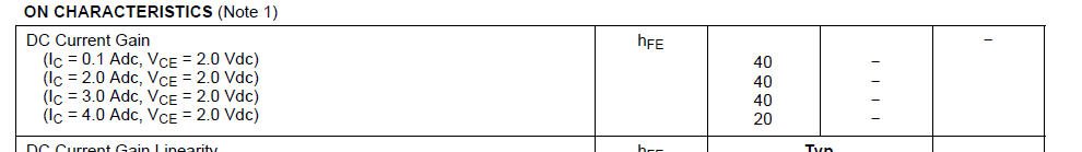
Attached pic shows that min Hfe is 40.
edit:
You must have meant the chart (also attached).
The way i see it is the chart shows typical value. It does not guarantee minimum value.
Attached pic shows that min Hfe is 40.
edit:
You must have meant the chart (also attached).
The way i see it is the chart shows typical value. It does not guarantee minimum value.
Attachments
Last edited:
So the chart is there for show? False advertising? What is its purpose if it must be ignored completely? What is "typical value" ? I have 60 or more transistors and not one falls in the chart. That is misleading, underhand, false.
If Hfe would meet the datasheet graphs, it would be a Paradise 🙂
In the real world tolerances are huge. So, we have to design our circuits in a way, that they can operate within these "uncertain" conditions.
Datasheet - is just a "rough indication"... unfortunately
Matching helps, but it's not always possible to match precisely enough.
In the real world tolerances are huge. So, we have to design our circuits in a way, that they can operate within these "uncertain" conditions.
Datasheet - is just a "rough indication"... unfortunately
Matching helps, but it's not always possible to match precisely enough.
for starts you may take your complain directly to onsemi ...it would be very interesting to listen what they have to say about this ...
In reality though here is how it works
The company produces semis with stamping and coding for their ratings both regarding type , date and hfe
Depending on the order, costumer,batch , partition , quality of materials used there might be hfe issues that is why most transistors normally state min normal and max
In retail though the demands between P and N can never be the same Quasi complementary amplifiers and applications must be eliminated from the face of the earth😀
so any of these big companies might run out of stock of NPN transistors will search and get NPN which obviously are other batch , other order other quality often other manufacturing plan and so on
Kind regards
Sakis
The Hfe stated is Minimum. No problem.
The amplifier it is used in will have driver current control, this takes care of the higher than required Hfe by sensing the current produced by the device and adjusting the drive. I would suggest that if the Hfe was less, you would have a point to take up with the manufacturer.
The amplifier it is used in will have driver current control, this takes care of the higher than required Hfe by sensing the current produced by the device and adjusting the drive. I would suggest that if the Hfe was less, you would have a point to take up with the manufacturer.
I have complained to Farnell where most of the transistors have come from. I also bought another 40 transistors from RS just to make sure, after Farnell replied a bit arrogantly to me saying "we do not sell replicas, we only buy direct from manufacturer with no brokers in between". Anyway Farnell have recorded the complaint and have informed their warehouse of the problem. My next step would be to write to ON because there are advertising laws and they cannot print rubbish on their datasheets.
My next step would be to write to ON because there are advertising laws and they cannot print rubbish on their datasheets.
You will at best get a lesson about electrical parameters specification, and the difference between "minimum" (table in the data sheet) and the "typical" (beta vs. current graph in the data sheet) specifications. The purpose of the graph is not to specify beta, but to show the relative beta vs. Ic dependency, in particular with temperature as a parameter, and to show the Beta-Ic drop. Those graphs could be normalized to beta and still provide the same information.
After all, what would make you happy, to get devices with beta specified +/-5%? That could be done if you would pull your wallet and pay x10 (or more) the bulk price. Also, every semi company would be happy to sort and match your order by beta, if you would buy in the millions.
Get used to it, you are to these semi giants nothing but a nagging mosquito. They have a much bigger fish to fry than your audio stuff.

I would get the references up to date before acting out the Monty Python/dead parrot/retail outrage routine.
There are several datasheets on the web covering these parts but the current one (Sept, 2013) from On-Semi's site,
just covers the MJE15028G to MJE15031G range. You could only infer that On-Semi suggest Hfe typical value is
80 at 0.5 amp in fig. 6 but as already said, it's only indicative. There is certainly no promise there of anything
like 150, just a minimum 40 across the range of 0.1 - 3 amps Ic.
http://www.onsemi.com/pub_link/Collateral/MJE15028-D.PDF
BTW, one of the most important distinctions between recent BJT audio power types and ancient craptanium parts is
gain linearity and so lower distortion at high power. I think D. Self made that point clear enough many years ago.
So which is more important matching the HFE or matching the pair ?.
This is like engine BJP when you buy a bike they say X BHP.
You can never match that BHP number. I heard a variation of +-30% is common and to be expected be it engine bhp numbers or data sheets or any component.
This is like engine BJP when you buy a bike they say X BHP.
You can never match that BHP number. I heard a variation of +-30% is common and to be expected be it engine bhp numbers or data sheets or any component.
You are matching the pair Hfe, so both.So which is more important matching the HFE or matching the pair ?.
A of engine comparison, it´s like comparing oranges to apples.
Mechanical parts can be made with high precision, fractions of 1%, because they are made one by one (BIG difference) in high precision machinery, and we care only about physical dimensions which are easy to check, real time, or even to force; now if you start caring about intrinsic properties such as tensile strength, surface hardness, etc. , you will start to see huge differences.
You buy 100 bolts and stretch them to rupture in a test machine, they will definitely NOT break within 5% of applied traction force, and not even near datasheet stated strength, that´s for sure.
Of course, we expect all of them to stand more; otherwise manufacturer might be criminally liable if some structure comes down because of that,but that does not mean they will be very close to each other, production spread is a reality
Now on semiconductors which are made in bulk, hundreds to thousands on same wafer and lots of potential variations from one wafer to next, by difficult to control with precision processes and with intrinsic high variations, the Industry just has to accept a certain spread or manufacturing becomes impossible.
Just imagine putting a wafer with 6000 transistors inside a certain gaseous atmosphere and heating it up to get some gas diffusion into Silicon .... I bet wafer edge areas and wafer center do NOT get the same, to boot there is not a definite "frontier" but a center-to-edge gradation.
Almost by definition all those transistors will be different to some degree, should they junk 50% of them to pick the closest ones?
And even so ....
I see datasheets cover both ends: provide you with useful design data, AND also warn you about spread.
The proof of the pudding lies in the eating: Engineers have been working for DECADES with such datasheets, producing usable products sold by the millions.
I bet people at Farnell and ON must have been quite baffled (amused?) by the noobish complaint.
You can design your circuits to be less sensitive to hFE. If the composite hFE is “high enough” the open loop gain is dominated more by the VAS Early voltage than it is by output stage gain, for example.
Of course you are always free to buy as many transistors as you want and match pairs yourself. If you DO, you need to match them under close to actual use conditions (voltage/current). Testing beta at very low “transistor tester” currents often gives false readings for power transistors. hFE can be much lower in the micro amp range, especially for NPNs. NPN and PNP have different dependency on current. NPNs tend to start low, peak, then roll off. PNPs just roll off. With two NPNs you could match at low current and they might actually track. An NPN and a PNP - no way. Todays transistors are flattER than the old BD911, but you canna change the laws o’ physics.
If you measure 50 on the NPN and 150 on the PNP at 5uA, they may very well be both near 100 or 120 at 200 mA.
My only way of testing HFE is with a component tester. So yes what you guys posted makes total sense.
Since my component tester is open source. Maybe I can increase the current used by the tester.
Maybe thats something worth thinking about. Another option I guess would be to scope the input and output under use. (If thats even possible).
And I have observed what has been mentioned. in the first few posts. There is a huge huge variation in HFE.
Typically all the PNPs will match. All the NPN will match. But getting PNP and NPN to match lol. Ive not seen that so far.
So when I got started in audio I did google what a matched pair is. And I soon realised thats not happening.
Maybe ive not found run across the right transistor.
If people have found such matched pairs that would be useful info to have and we could all just use those in our design.
According to semiconductor physics and most texts, PNP/NPN matching simply cannot occur - don't expect it to any time soon either. Don't worry about it though, the world turns without it being concerned about this imaginary lapse of ideal behaviour.
As suggested, component testers operate for gain testing at levels of only a few milliamps which is usually fine for small signal applications. I assume you are aware that a 9V battery or miniature rechargeable battery for these, is only good for flea-power and no-way can you modify the microcontroller chip (that's all a typical component tester is inside) to pass more than that amount of current anyway.
You could re-design the test such that the component tester only samples and compares a small fraction of the currents in the test transistor, since it needs to operate with much greater current to give meaningful results at its expected power levels. However, the tester then takes a back seat as little more than a cheap display in comparison to the heatsink, clamps , precision power supply(s), clamps and jigs and some calibration etc. now needed to set up a proper procedure before testing anything that draws a lot more than 30mA from the supply.
Rod Elliott (RodE here) developed such a semi tester many years ago. It's not a simple project but studying the design and article will at least shed light and understanding of what's involved in testing power semis and semis generally - the why and how to DIY.
It's not the latest microprocessor-tech but we are looking to see principles of operation and accuracy limits rather than stare in awe at little slabs of plastic with lots of metal legs. https://www.sound-au.com/project31.htm
Last edited:
The inevitable technological spread within certain limits. If you need a match, make a selection from a lot or different lots.So which is more important matching the HFE or matching the pair ?
The exact selection is made with the help of a characteriograph (or by several points)))
There is no such thing as one Hfe for a transistor.
I designed a transistor matcher and curve tracer and the Hfe changes all the way along the curve.
It varies with different currents. Quite often its higher with lower currents so those cheapo battery powered transistor testers are meaningless.
I designed a transistor matcher and curve tracer and the Hfe changes all the way along the curve.
It varies with different currents. Quite often its higher with lower currents so those cheapo battery powered transistor testers are meaningless.
FWIW I regularly use many power transistors (built and delivered over 14000 Guitar Bass PA Keyboard amplifiers, do the Math) so LONG ago designed and built my very simple and realistic meter/tester.
Simple because it tests them at one value only, a very useful one to me : Ic 10A@4Vce so saturation voltage while putting out maximum current out in a 100W into 4 ohm amplifier (my main breadwinner) which to boot is a very common datasheet value.
Talk about killing 2 birds with 1 stone.
Some details:
* I use half LM358 which is cheap and abbundant (and I always have lots of them) ; the other half is neutralized by shorting output to -IN and connecting +IN to some reference level (such as the 1V reference used here) or ground.
LM358 is happy with single supply and has no problem grounding unused input.
Most "Better" Op Amps are not happy with that.
* +12V and +5V rails come from an old junked PC supply, everybody has one or more laying around.
* TIP31 is heatsinked
* DUT (Device Under Test) "should"
To test many, quickly, I built a heatsink with a "quick clamp" to press it , to speed things up I use no mica and "termal paste" is a drop of oil or kerosene.
Good enough for a test which lasts all of 5 seconds at most, and wiping it out is easy peasy while white thermal paste is messy annoying.
Brave souls can simply press transistor with their thumb, test lasts only 5 seconds (until you get a stable reading in the meter) and it has no time to heat up.
* the CPU is of the wet soggy type, usually known as B.R.A.I.N. ....... meaning YOU do the Math.
Ic is guaranteed 10A, you measure Ib; Hfe is 10A/Ib ..... simple huh?
* results are accurate , reliable, and USEFUL, since they are taken under real world conditions, which you will use in your amplifier; of course it´s easy peasy to modify it for other currents.
* Pocket calculators are allowed/encouraged.
Schematic:
- Home
- Amplifiers
- Solid State
- Datasheet and reality