Post here for your SlewMaster builds!
Hi Quan,
I think you may have misread the silk screen, there are no 0R22 resistors on the Symasui IPS, but I could see the confusion with R22 being a 22R value. When I put the value on the silk screen it will always be 'inside' the silk pattern for the device, the schematic designator will always be visible when the device is installed.
I would do a basic matching of the TO-92 devices, no need for obsessive pursuits.
Hi Jason. I would like 2+ Symasui please. Do all transistors need to be match?( also those 0.22R resistors).
Quan
Hi Quan,
I think you may have misread the silk screen, there are no 0R22 resistors on the Symasui IPS, but I could see the confusion with R22 being a 22R value. When I put the value on the silk screen it will always be 'inside' the silk pattern for the device, the schematic designator will always be visible when the device is installed.
I would do a basic matching of the TO-92 devices, no need for obsessive pursuits.
Last edited:
Hi Jason, sorry i meant to refer to the OPS trannies and their output resistors 0.22R.
Quan
Ah, I see. No requirement to do any real matching in the OPS. Of course if you have the parts in quantity you could do some selection but it isn't needed. Sorry for the confusion.
Ah, I see. No requirement to do any real matching in the OPS. Of course if you have the parts in quantity you could do some selection but it isn't needed. Sorry for the confusion.
No problem, thanks.
Quan
Nice one Jason. Do you have a quick guide to test IPS prior to hooking up to OPS boards. I 've read on the thread about tying FB/VD+/VD- via 470R and testing it this way?.
Quan
Quan
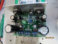
Resistors can be used to verify the VAS current but the IPS is best tested without them. Just tie the NFB, PD and ND together and measure the output off the NFB point. You will notice with the CFA designs the VAS is heavily loaded by the low impedance FB network and this is less of an issue with the VFA designs. Still, it is nice to be able to run the IPS designs independently.
Thanks Jason, can you show it on simple diagram ?.Resistors can be used to verify the VAS current but the IPS is best tested without them. Just tie the NFB, PD and ND together and measure the output off the NFB point. You will notice with the CFA designs the VAS is heavily loaded by the low impedance FB network and this is less of an issue with the VFA designs. Still, it is nice to be able to run the IPS designs independently.
Quan
Hi Jason, may be these questions should be over the other thread but does q7 and Q10 on CFA IPS needs to be thermocouple?. How much heat sink do they need?. I can see the space for a flat pierce of aluminum only. I have a couple of small finned heat sink size 2cmX1cmX0.4mm. Would they be ok for those mje 340/350?. TIA.
Quan
Quan
Hi Jason, may be these questions should be over the other thread but does q7 and Q10 on CFA IPS needs to be thermocouple?. How much heat sink do they need?. I can see the space for a flat pierce of aluminum only. I have a couple of small finned heat sink size 2cmX1cmX0.4mm. Would they be ok for those mje 340/350?. TIA.
Quan
Very minimal heat sinking is required, so a small piece of aluminum sheet is fine. I tested mine without any heat sink at all at +/-45V without any issue.
Thanks Jason. I am afraid of not much help to any suggestions. My electronics is pretty basic only high school stuff and my day job is mainly medical. I am learning slowly ,sorry very slow😀.
Quan
Quan
Hi Jason, can you check the template for the OPS drilling. I downloaded the v2 but it does not seem to match up properly with the board.
Quan
Quan
The v2 template is for the 5P OPS. I will be busy for most of the day today but can update the template to show the 2P OPS ( or just make a dedicated 2P version) tomorrow.
Quan,
You got the first run of the OPS boards so you need the template I put up prior to the v2 file.
Try this:
http://www.diyaudio.com/forums/atta...-rumble-slewmonster-5p-ops-drill-template.pdf
You got the first run of the OPS boards so you need the template I put up prior to the v2 file.
Try this:
http://www.diyaudio.com/forums/atta...-rumble-slewmonster-5p-ops-drill-template.pdf
Last edited:
Quan,
You got the first run of the OPS boards so you need the template I put up prior to the v2 file.
Try this:
http://www.diyaudio.com/forums/atta...-rumble-slewmonster-5p-ops-drill-template.pdf
Many thanks Jason.
Quan
Sorry Jason . I actually got the second run of the OPS. I have check both templates and they are the same ( from both downloaded version).. The width of the board on template measured 7cm and the v2 OPS board measured 7.5cm. Can you double check?.
Quan
Quan
Make sure you are printing at 100% and not allowing any scaling. There are two distinct templates, one for the first run which I was pretty sure you got and one for the final, current, version. The holes for the PCB corners and the main output VBE positions are different so it is important to be sure which ones you have. I have printed the templates and can verify they line up. If need be I can send them to you in a different format. PM me with an email address and I'll send you both versions in PDF and an image format (bitmap maybe - I have to see what export options the CAD program has).
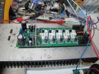
Hi Jason, i just don't want to clog up the thread but running into some trouble with the OPS. I used 15kR across V/PD, ND/-V. I could not get any measurement at RE(0.22R). R113 (68R) measured 5.67V!!!, R110 measured 11.2V. The pre-driver HS toasting hot with alum plate.I used all parts as per your schematic. BTW IPS(CFX-3H) is good and ready to go.
Quan
Quan
Well, 15k should do for most testing purposes with respect to running the OPS on its own. You say you have tons of bias in the pre-driver / driver but none in the outputs? What are you running for rail voltages?
You have connected the two G2 points with a wire under the board?
You have connected the two G2 points with a wire under the board?
Last edited:
Thanks Jason. Yes i did connect the ground together and connected 114/115. The rails are +/- 67VDC. I measured across 0.22R but got nothing despite adjusting the bias. The R113 (68R) measured >5V, R110 measure 11.2V.Well, 15k should do for most testing purposes with respect to running the OPS on its own. You say you have tons of bias in the pre-driver / driver but none in the outputs? What are you running for rail voltages?
You have connected the two G2 points with a wire under the board?
Quan
- Home
- Amplifiers
- Solid State
- SlewMaster Builds

