Someone recently asked how much distortion might be introduced by using a couple of zeners as voltage limiting elements at the output of a preamp. Since this isn't something that can be guessed at from an armchair, everyone went very quiet. I was interested to know the answer, so I did a few measurements using some ordinary 10V and 16V zeners. There's nothing special about the zeners (BZX79Cxx). I just chose them because I had them to hand, and they seemed like suitable values that might be used to protect downstream solid-state equipment.
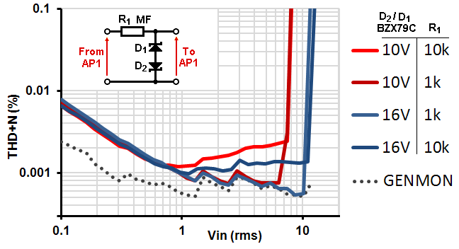
Here you can see distortion versus level at 1kHz (measurement bandwidth <10Hz-80kHz, 100k load resistance). The rise below 1Vrms is purely noise added by the series resistor. Above this distortion rises, but is lower than most valve distortion up until the clipping point. I was actually surprised at how well the clipping point is defined.
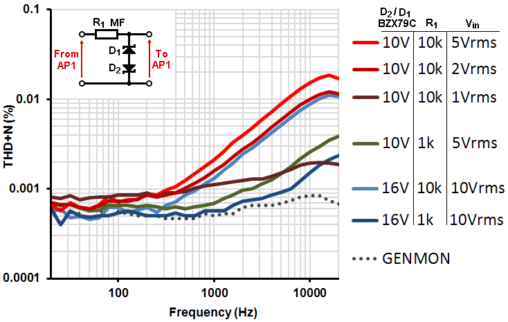
Here you can see distortion versus frequency at different signal levels below the clipping point. Offhand I suppose the rise with frequency is due to nonlinear diode capacitance. For signal levels up to 1Vrms the distortion is certainly less than valve distortion.
Above this, distortion at high frequencies could intrude, but since high frequency contect on music typically falls at 40dB/octave above 2kHz, I doubt you would ever hear anything. How often do you send out signals to SS equipment at 5Vrms?
Unsurprisingly, for the least distortion, use the highest zener voltage you can get away with, and use the smallest series resistance.
Here you can see distortion versus level at 1kHz (measurement bandwidth <10Hz-80kHz, 100k load resistance). The rise below 1Vrms is purely noise added by the series resistor. Above this distortion rises, but is lower than most valve distortion up until the clipping point. I was actually surprised at how well the clipping point is defined.
Here you can see distortion versus frequency at different signal levels below the clipping point. Offhand I suppose the rise with frequency is due to nonlinear diode capacitance. For signal levels up to 1Vrms the distortion is certainly less than valve distortion.
Above this, distortion at high frequencies could intrude, but since high frequency contect on music typically falls at 40dB/octave above 2kHz, I doubt you would ever hear anything. How often do you send out signals to SS equipment at 5Vrms?
Unsurprisingly, for the least distortion, use the highest zener voltage you can get away with, and use the smallest series resistance.
Last edited:
Merlin,
The THD rise with frequency is possibly the most remarkable part of your study. As the hearing is more forgiving w.r.t. distortion in the low frequencies than in the high frequencies, this irregularity will be noticed. Does a equal-loudness contours curve exist for distortion?
The THD rise with frequency is possibly the most remarkable part of your study. As the hearing is more forgiving w.r.t. distortion in the low frequencies than in the high frequencies, this irregularity will be noticed. Does a equal-loudness contours curve exist for distortion?
If the distortion levels were 10 dB higher I'd be more inclined to agree you could hear something. I agree with Merlinb about the source of the distortion. Even varicaps go nonlinear as applied voltage rises.
Hi, did you run the various measurements with the series resistors in place but without the zener diodes?
It would be good to know the effect of the series resistance on your test set's accuracy.
It would be good to know the effect of the series resistance on your test set's accuracy.
Yes, for your reference:Hi, did you run the various measurements with the series resistors in place but without the zener diodes?
An externally hosted image should be here but it was not working when we last tested it.
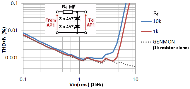
(Red 1kohm, blue 10kohm)
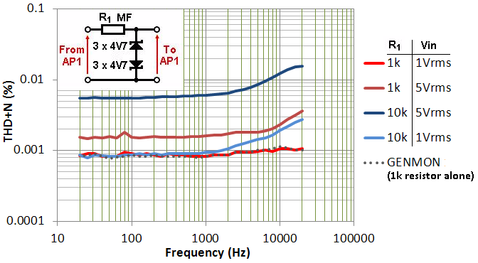
For interest, here is the effect of using six 4.7V diodes, which are roughly equivalent to using two 16V devices. These should be true Zener diodes, however. The clipping point is clearly much softer than the avalanche diodes used earlier.
Thank you so much ! I wouldn't have the equipment to do those mesurement, and I needed this information.
I have a tube preamp and I need to limit the tension at startup. This'll do the job just fine 🙂
I have a tube preamp and I need to limit the tension at startup. This'll do the job just fine 🙂
Merlin, the soft clip aspect of the 4V7 string versus 16V part is consistent with tests I did to clone a Magnatone varistor, where the aim was to identify parts with as soft a knee as possible. The hassle I had was that the varistor needed a 110V capability so I ended up with 32 of 3V9 zeners in series - at least the clipping action here only needs a few zeners in series.
If you are not afraid of compexity: id create some +-5V rails and two 1n4148 to clamp to them. Those small signal diodes have much lower capacitance.
This does work, but you do have to pay attention to how those rails are implemented. You will want some energy storage (capacitor) and a load, at least a small one. If you just try to feed a signal backwards into a 3 terminal voltage regulator directly, for example, the output voltage will rise and you won’t clamp where you think you are supposed to. If you have an energy reservoir and some way to dissipate it, the clamps work as expected.
Id use two 1206 MLC”s for the capacitor bybass, 10u and 100n will do the trick after looking at the impedance curves on those.
I buy TL431 by the 100s and use them to replace zeners in all kinds of things. best IC ever.
I buy TL431 by the 100s and use them to replace zeners in all kinds of things. best IC ever.
- Home
- Amplifiers
- Tubes / Valves
- Zener diodes as protection clippers