Several years ago I picked up a used broken Sony Xplod amp Model XM-2185 GTX rated 165W x 2 into 4 ohms. Poking the volt meter around I discovered that the SMPS was still pumping out around +- 38 volts DC. But could not figure out what else was wrong with it. So I tossed it to the side for another day.
Flash forward to another day and I have a co worker who wants a cheap car audio upgrade for his newer Nissan Versa keeping the stock head unit. Well let's see what I have laying around the house: How about what I picked up a while back at one of Part's Express buyout/closeouts: 4 ohm Peerless SDS woofer Peerless 835004 SDS 6-1/2" Woofer 4 Ohm | 299-250 for like $10 each. Plus some tweets and a leftover crossover (I have active in my car) and I have half the problem solved.
As for amplification. Well, what can I do with the old Sony amp with working power supply? First, I got lucky and found the service manual: Sony XM2165GTX Service Manual free download,schematics,datasheets,eeprom bins,pcb,repair info for test equipment and electronics It's using a TL594 as SMPS controller feeding 6 power MOSFETS (FKV550N) 3 each leg. Specs on the MOSFETs say 50v/50A. Also from the look at the PC board and the circuit diagram, I could cut the board in half and have just the SMPS with a single row of the MOSFETs plus the two double diode rectifiers all sharing the one side of the heat sink/case. So I decided to cut the board and the metal case to provide heat sinking as well as protection. I also wired the +- DC output to what were the normal speaker outputs for one of the no longer used two channels. I'll post pictures of this abomination later. Yes, its pretty fugly. Edit: As promised, don't laugh:
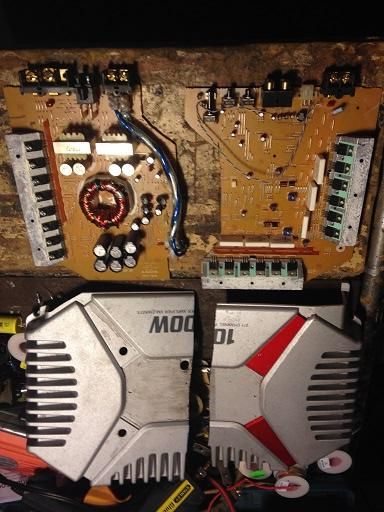
(Above: Pic of split Xplode amp with SMPS power coming out front previously speaker terminals.)
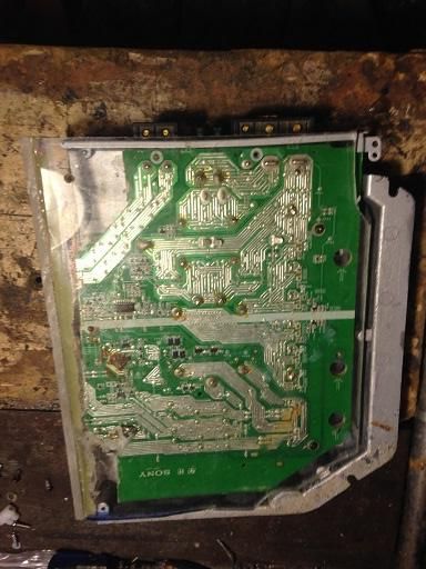
(Above: Bottom view of SMPS with homemade plexiglass cover.)
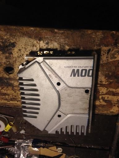
(Above view of SMPS portion of XPlode amp) Soon to painted flat black and hidden.
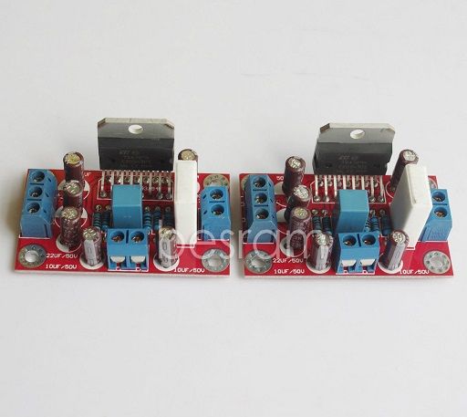
Now I have power, what can I do with it and on the cheap? How about a chip amp? A little ebaying brought up a pair of TDA7294 boards assembled from China for like <$17 including shipping. Can't beat that!
So I've been wondering about heat sinking the chip amps and mounting the resulting mess in this guy's car. The solution I've come up with is building a shelf under the rear deck (in the trunk) to hang down at most 3 to 4 inches to hide the ugly SMPS amp and the chip amps. As for cooling, I have a big old CPU heat sink from a Dell that was being tossed at the office. Looks like:

I probably could put both chip amps on it, but I'm going to pick up another heat sink just like it (from ebay). So my plan is to have the old SMPS power supply on one side of the shelf and on the other have two of these heat sinks on their side with a 80mm (or so) case fan blowing thru the two of them. I also have a couple extra surplus big 'ole electrolytic caps like 30,000uF @ 50v to shore up the wimpy 3 x 2200uF per leg caps on the original SMPS board. Of course, mounted externally to the SMPS since they are kind of big.
My thinking is on most car amps the SMPS and all channels being amplified are all on the same heat sink/chassis. Splitting the SMPS from the amplification would reduce size (two smaller thingies are easier to hide/install than one big one). And the split would run cooler since the heat is spread and separated. Putting the chip amps apart from each other would also help.
I'll probably share this project with the guys over at DIY Mobile audio as well. I have a spreadsheet with the totals I have spent on this project which includes new 8 gauge power wire, fuse, ring terminals, 3 sheets of RAAMmat deadener. Total so far is under $150.
Flash forward to another day and I have a co worker who wants a cheap car audio upgrade for his newer Nissan Versa keeping the stock head unit. Well let's see what I have laying around the house: How about what I picked up a while back at one of Part's Express buyout/closeouts: 4 ohm Peerless SDS woofer Peerless 835004 SDS 6-1/2" Woofer 4 Ohm | 299-250 for like $10 each. Plus some tweets and a leftover crossover (I have active in my car) and I have half the problem solved.
As for amplification. Well, what can I do with the old Sony amp with working power supply? First, I got lucky and found the service manual: Sony XM2165GTX Service Manual free download,schematics,datasheets,eeprom bins,pcb,repair info for test equipment and electronics It's using a TL594 as SMPS controller feeding 6 power MOSFETS (FKV550N) 3 each leg. Specs on the MOSFETs say 50v/50A. Also from the look at the PC board and the circuit diagram, I could cut the board in half and have just the SMPS with a single row of the MOSFETs plus the two double diode rectifiers all sharing the one side of the heat sink/case. So I decided to cut the board and the metal case to provide heat sinking as well as protection. I also wired the +- DC output to what were the normal speaker outputs for one of the no longer used two channels. I'll post pictures of this abomination later. Yes, its pretty fugly. Edit: As promised, don't laugh:
(Above: Pic of split Xplode amp with SMPS power coming out front previously speaker terminals.)
(Above: Bottom view of SMPS with homemade plexiglass cover.)
(Above view of SMPS portion of XPlode amp) Soon to painted flat black and hidden.
Now I have power, what can I do with it and on the cheap? How about a chip amp? A little ebaying brought up a pair of TDA7294 boards assembled from China for like <$17 including shipping. Can't beat that!
So I've been wondering about heat sinking the chip amps and mounting the resulting mess in this guy's car. The solution I've come up with is building a shelf under the rear deck (in the trunk) to hang down at most 3 to 4 inches to hide the ugly SMPS amp and the chip amps. As for cooling, I have a big old CPU heat sink from a Dell that was being tossed at the office. Looks like:
I probably could put both chip amps on it, but I'm going to pick up another heat sink just like it (from ebay). So my plan is to have the old SMPS power supply on one side of the shelf and on the other have two of these heat sinks on their side with a 80mm (or so) case fan blowing thru the two of them. I also have a couple extra surplus big 'ole electrolytic caps like 30,000uF @ 50v to shore up the wimpy 3 x 2200uF per leg caps on the original SMPS board. Of course, mounted externally to the SMPS since they are kind of big.
My thinking is on most car amps the SMPS and all channels being amplified are all on the same heat sink/chassis. Splitting the SMPS from the amplification would reduce size (two smaller thingies are easier to hide/install than one big one). And the split would run cooler since the heat is spread and separated. Putting the chip amps apart from each other would also help.
I'll probably share this project with the guys over at DIY Mobile audio as well. I have a spreadsheet with the totals I have spent on this project which includes new 8 gauge power wire, fuse, ring terminals, 3 sheets of RAAMmat deadener. Total so far is under $150.
Last edited:
The guys on the chip-amp forum could tell you definitively but I think the voltage is too high for a 4 ohm load for those ICs. You may have to regulate the voltage down to a bit under ±30v.
You may also want to ask how sensitive these are to extended wire lengths from the power supply. You may have to add capacitors at the power input terminals of the boards.
I don't know if there is a problem with these ICs and counterfeiting (problem with some semiconductors) but the ICs alone are about $5 each.
Thanks Perry for bringing up one of my concerns with this particular SMPS and that is the higher voltage. Recommendations on regulating it? I've briefly looked into it and closest I got was some rather expensive 3 pin power adjustable regulators that I'd have to use multiple of because individually they can't handle too many amps. Plus then, I have something else to heat sink, although I do have room on top of my ugly XPlod case.
I thought there was a way of adjusting via tweaking one of the pins of the controller (pot and resistor to + and ground). Pictures of ebay SMPS they claim to be adjustable have a trimmer pot on them for I guessing this purpose.
Yes, I was also worried about having the SMPS voltage output go too far. That's why I'm adding the 30Kuf caps to it. Also most of these amp boards have a pair of caps on the power feed (usually a pair of 1000uf).
BTW Perry: Been awhile but I've read thru the great, great tutorials/write ups on Basic Car Audio Electronics that you have linked on your sig line. Maybe I should reread the SMPS section. I minored in EE, majored in Computer Science and its been a few years and I don't use my EE knowledge often enough.
Looking at the diagram, connecting a potentiometer from the positive rail to ground and using the wiper to feed pin 16 should do it. To simplify, for now, remove the connections to the 10k resistor to ground and the connection to the opto-coupler (you can remove them from the circuit if that's easier than cutting traces). You want the output of the pot to be 3v (to match pin 15) when the rail voltage is at the desired voltage.
If you remove the opto-coupler and leave R844, connecting an 83k ohm resistor between pads 1 and 4 of the opto-coupler, it should give you about the right voltage.
If you remove the opto-coupler and leave R844, connecting an 83k ohm resistor between pads 1 and 4 of the opto-coupler, it should give you about the right voltage.
Thanks a million Perry! That's just the kind of info I needed. I'll give it a whirl and hope I don't let any of the smoke out of the SMPS 🙂
Project follow up: I got the TDA boards in. Didn't realize how frickin' small they are and that out of this one IC, not much bigger than a couple TO220 devices can do 50W+. I'll post some pics of them mounted on the great big CPU heat sinks. I wonder if I'll really need a fan with all those heat pipes and radiating fins.
It was also nice of the China ebay dudes to include a screw, nonconductive insert (washer like) and a thermal pads for the chips. Downside of the board is if you look: where are the big 1000uf caps on the supply side? A circuit diagram was also not included.
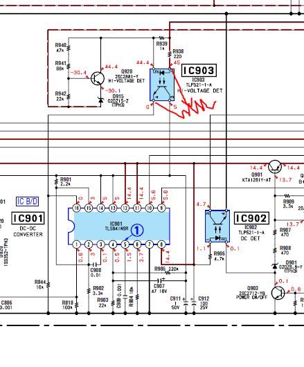
I did what I thought Perry suggested in his last sentence for voltage adjustment and put a 100K trimmer pot dialed for around 83K between 1 and 4 of the opto-coupler (after removing it). Now the voltage jumps comes up for a few seconds and then drops, then comes back up. What I did is shown roughly below (with my freehand red trimmer pot there).
Do I also need to cut the R939 there above the opto since it's connected also to pin 1 (of the opto) and the circuit labeled: "Hi-Voltage Det"? I haven't had a chance to measure the voltage (for 3v) feeding pin 16 of the TL PWM chip.
Thanks in advance for your help (Perry).
It was also nice of the China ebay dudes to include a screw, nonconductive insert (washer like) and a thermal pads for the chips. Downside of the board is if you look: where are the big 1000uf caps on the supply side? A circuit diagram was also not included.
I did what I thought Perry suggested in his last sentence for voltage adjustment and put a 100K trimmer pot dialed for around 83K between 1 and 4 of the opto-coupler (after removing it). Now the voltage jumps comes up for a few seconds and then drops, then comes back up. What I did is shown roughly below (with my freehand red trimmer pot there).
Do I also need to cut the R939 there above the opto since it's connected also to pin 1 (of the opto) and the circuit labeled: "Hi-Voltage Det"? I haven't had a chance to measure the voltage (for 3v) feeding pin 16 of the TL PWM chip.
Thanks in advance for your help (Perry).
I didn't think to question the numbering on the schematic diagram layout but they have it wrong. What are the chances?
The pot you inserted in place of the opto-coupler has to connect between the positive 45v output and pin 16 of the TL494. Remove the pot.
Use your meter to find the pad for the opto-coupler that directly connects to pin 16 of the 494.
Power the supply up and find the positive 45v terminal for the opto-coupler.
Connect the wires for the pot to those pads of the opto-coupler's location.
My only question is why did you saw the heat sink in half? Seems like you could have used it as the mounting point for the new boards. What did I miss?
😕
😕
Speaker: You missed the fact I had limited amount of space and wanted stealth. Hardly enough for the full sided amp. Plus I wanted cooler running with two (make it three, SMPS and two amp modules) smaller heat generators rather than one big one.
Project update: I kind of gave up, or more accurately, put to the side the SMPS because despite my efforts (and Perry's help) , I could not get it to lower voltage to what the chips amps need. But I'm beginning to wonder if it doesn't have other problems. I'll save it for a higher power amp for sub duty.
In the meantime I cannibalized another amp for its SMPS which put out closer to +- 30v and was smaller. Typical 6 x IRFZ44N design. Bench tested OK. Found an old small Punch45 case that just about perfectly fit the new SMPS. Got the SMPS board in, the TO-220s screwed in (with thermal pads underneath) with a custom made aluminum bar across them drilled to fit. All ready to go and I power it up to test and.... nothing! Yes, I did my best to isolate the board from the metal case.
I can't win on this project! I have the two TDA boards all hooked up to their respective heat pipe CPU coolers and was ready to test both with woofers/tweeters (with xover) all attached. I had tested one amp with the newer SMPS outside the case and no turn on/off noise (unlike the other SMPS).
Add that to the fact the summer is upon us and the Texas heat makes it a bit less bearable to work in my garage workshop this time of year other than early mornings and after sundown.
On top of that, like most guys (I think), I always have multiple projects going. The other is my wife's HHR SS (turbo) sound setup. There I have a bit more room and about ready to install a four channel Cerwin Vega amp after getting the install supplies in via mail order/ebay. Speakers have already been replaced. Write up is on Wife's SS Pioneer System: Install Speaker Upgrade, Door Deadening - Chevy HHR Network
I did miss that about the stealth aspect for the Sony variant.
So, did you fry the TDA7294 boards? Don't get discouraged, yours is a very cool project. I want to know how the modules work when you get it complete. I am most curious what/if the turn on/off transients will be like.
So, did you fry the TDA7294 boards? Don't get discouraged, yours is a very cool project. I want to know how the modules work when you get it complete. I am most curious what/if the turn on/off transients will be like.
No, the amp boards are OK (I think). Its the newer SMPS that might have fried. Like I said, on the bench prior to putting into old case, it turned on and off nicely with no pops, whines, etc. At one time I was afraid I'd have to figure out a way to using the TDA chip's turn on/mute pins. The other (Sony) SMPS whined (thru the amp to the speakers) like a spoiled child when I cut the 12v (I use a sealed gel cell originally for a UPS as my power source).
One thing I don't really like about these (cheap) boards, besides the lack of power supply decouplers) is the rather small terminal connectors on it. Ever try and put something like a 14 or 16 gauge wire into one of these small terminal holes that look like they are made for less than 18 gauge? Of course, small is OK on the input, but for power and output, I would have liked something a bit bigger diameter.
I'm going to read some more of Perry's excellent web site on Amp repairs, specifically on SMPS and see what's happening with mine. No visual damage that I could tell, getting +12 where I want it, just that turn on signal does nothing for it when checking the power outputs. Its got the common TL494 SMPS, so replacing it or any of the MOSFETs/Dual Diodes is fairly easy and cheap.
What I'm really curious about is how hot will the heat pipe style CPU heat sinks really get and will they require additional fan cooling. It was a bit tricky drilling for the mounting screw on the bottom as to not hit and pierce one of the heat pipes. Do that and the heat sink is basically scrap metal. I'll have to post some pics tonight of these tiny boards on these monster heat sinks.
My opinion... Go back to the Sony supply. It may take a bit of troubleshooting but it should be fairly easy to find the problem.
Does it still has any function to but that lot power in your car? . Comparing a new new car from a average pricepoint from 50.000, with just jbl. b&w . They also go loud and have a nice clear sound. But those twp pcb's ain't expensive and you can allways use them for something else....
I have Swan M50w amplifier with sub woofer 120w 8 ohms speaker.
when switched on, heavy hum from sub woofer but amplifier is ok with good sound when sub woofer disconnected.
it uses tda 7294 for subwoofer and tda 7265 for ammplifier with common external digital volume with press muting.
dual power is ok +/-22v and +/-32v seperately.
I get -42v at pin 14 of tda 7294.
between pin2&14 22k resistor and between pin 14 and earth resister 5ohms in series with 104 cap
I blindly replaced tda7294 but nothing materilized.
i have noticed sparks at terminal pin2&6.
please suggest suitable guidelines.
Please don't post in a repair thread that was started by someone else unless you are trying to help them.
Start a new thread.
Start a new thread.
- Home
- General Interest
- Car Audio
- DIY Cheap Car Amp: SMPS from broken amp + TDA7294 Chip amp boards