I recently came up with an interesting approach to make a tube (triode or pentode) lose it's Rp. (ie, go to very high output impedance) This might seem pointless, but if you want to control an amplifier's output impedance via feedbacks, it can be usefull to remove the effect of the usual varying tube Rp. This could be especially useful for SET type amplifiers where only one tube is operating (and varying it's Rp). Class A P-P amps have some (but not perfect) built in compensation for this, since one tube picks up as the other tube lets go. Class B P-P amps have far less compensation of output Z (before global feedback applied) due to non overlap of tube conduction, and that is responsible for some of the 3rd harmonic distortion they produce.
How this works is to operate g1 in positive territory (exclusively, so only some zero bias triode tubes will be suitable, most pentodes can be configured though, via low screen V, and some conventional triodes might be configurable via low plate V if they can supply enough current), and drive it with a controlled current source drive. (instead of the usual voltage source drive) The positive grid 1 intercepts a near constant small fraction of the cathode current stream (at least until the plate V dips down low enough to approach the region of g1 voltage). Lets call 1/Beta the numerical factor for fraction of plate current captured by the grid1. (so Beta is the current gain for the tube in this mode) The current source drive will automatically adjust the g1 voltage to obtain its requested grid current (and so results in the plate current at Beta times that).
So, looking at a triode, any variation of voltage on the triode's plate will automatically be met with 1/Mu opposite voltage variation on the positive grid 1 in order to satisfy the grid current requested. A pentode will operate similarly in positive g1 current drive, just with less voltage variation on the grid, due to the effective high Mu of a pentode. When the plate voltage does not effect the tube's current, we have high impedance, the intended result.
The driver circuit could be a linearized (high gm, cathode degenerated) pentode stage, maybe differential. Or a triode stage with low Rp and some series resistance to the output tube grid.
With the output stage's Rp gone, external combined V/I global feedbacks can be used to set an output impedance. (or for a low feedback design, only a weak local V feedback would be required, since the stage is already providing controlled current. This would set up a current per output voltage mode instead.)
This all would be useful if one wanted to drive a speaker with "critical damping" impedance, say.
g2 current drive might also work, but I'm not sure how well it will hold a constant Beta, since plate V will be dipping down to that V range easily. Beta would be expected to droop some when amplitude is high.
One could even get tricky, and make the output impedance vary in a specified way with amplitude or frequency to control some speaker in a way to compensate for its characteristics. This could be accomplished by a finite output resistance in the driver stage, maybe frequency affected, or frequency controlled outer impedance control feedbacks.
Just as a note. Using V and I global feedbacks have been used historically to control amplifier output impedance. But they typically require high loop gain in the amplifier to make them effective. This current (pun) approach allows one to accomplish similar effects for low or no feedback designs. More likely appealing to the SET crowd or low feedback group.
Last edited:
Can't be a good idea because when you go in a positive region you are going in a not linear region
Walter
Walter
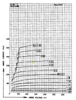
I was looking at the data sheet for an 807 look-alike, the 5B/255M, and there are plenty of graps with positive grid data, and they look reasonably linear to me.
5B/254G etc
5B/254G etc