Hi there,
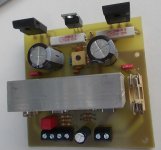
I have built a test board for the LME49830, exactly according to the datasheet. Only conventional components were used, no SMD.
The board works. The sound is warm and clear.
If anyone can use it, I can upload the layout. I do not want it to develop. It was just for fun, the LME49830 has a friend gave me.
regards Olaf
Attachments
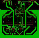

I can upload the PDF or the sprint-layout-file.
Etching I do just for me and that's more than enough...
Sorry.
Etching I do just for me and that's more than enough...
Sorry.
how is the distortion performance? any THD curves you can post? Ive seen the comparison between all the LME series but with IRF how is the distortion performance and at what BIAS?
You can buy the Nat Semi board on Ebay from at least one HK/Chinese vendors -- they are legit Nat Semi stock.
how is the distortion performance? any THD curves you can post? Ive seen the comparison between all the LME series but with IRF how is the distortion performance and at what BIAS?
Hi,
I tested the chip with +-32V. I set the bias to 5V without further experiments. On the oscilloscope no distortion can be seen. But I have no professional equipment.
regards
Last edited:
Very nice pcb design with all the features. Congratulation.
Makes me want to replicate.
Regards Olaf
Makes me want to replicate.
Regards Olaf
Looked such a fun little project, that I just had to make one too...
Very nice
palstanturhin,
Your design is excellent! You could sell the PCB for at least $25 each.
I like your design better than the National PCB in AN-1850.
http://application-notes.digchip.com/006/6-8907.pdf
Your design is excellent! You could sell the PCB for at least $25 each.
I like your design better than the National PCB in AN-1850.
http://application-notes.digchip.com/006/6-8907.pdf
Looked such a fun little project, that I just had to make one too...


Hi,
Nice layout.
Hi Phil!
Schematic in post number 1 http://www.diyaudio.com/forums/solid-state/244746-testboard-lme49830.html#post3678453
I realized I have removed resistors RE1/RE2, do not let that bother you...
I still have not tested the board myself.
Schematic in post number 1 http://www.diyaudio.com/forums/solid-state/244746-testboard-lme49830.html#post3678453
I realized I have removed resistors RE1/RE2, do not let that bother you...
I still have not tested the board myself.
Hi folks,
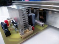
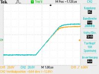
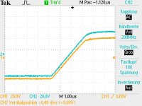
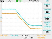
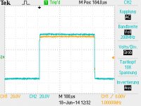
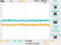
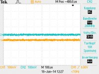
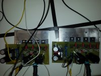
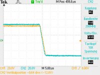
I did some measurements between IRFP9240 / IRFP240 and ECX10P20R / ECX10N20R MosFET.
The Layout of the IRFP board is capable to use Toshiba MosFETS. So I left space to add diodes between Source and Gate. Don't be irritated if you see the pictures. Note, IRFP MosFETs do not need such diodes.
The ECX MosFETs have a different PIN-Layout, this is the only change between both boards. Feel free to use an distribute it.
I also add the power supply unit. They have 2.5mV AC, it is quite good .
I drove both boards with a -50V +50V rail voltage. So you have 100V, so be careful. From the TI recommendations, you should not go higher then -60V +60V. There are some thermal aspects that have to be consider by higher voltage, like active cooling.
cya
Phil
Attachments
-
eagle_files.zip268.8 KB · Views: 154
-
 pulse_raise_compare.JPG89.1 KB · Views: 148
 -
 pulse_raise.JPG94.7 KB · Views: 150
 -
 pulse_fall2.JPG94.5 KB · Views: 158
 -
 pulse.JPG88.3 KB · Views: 168
 -
 noise_open_output_2.JPG101.8 KB · Views: 232
 -
 noise_open_output.JPG94.2 KB · Views: 339
 -
 Test_setup2.jpg460.8 KB · Views: 605
 -
 Test_setup.jpg419.7 KB · Views: 620
 -
 pulse_fall_compare.JPG90.5 KB · Views: 132
Hi folks,
I did some measurements between IRFP9240 / IRFP240 and ECX10P20R / ECX10N20R MosFET.
Sorry what I forgot to mention, the yellow line on the TEK is the IRFP board the blue line the ECX board.
cya
Phil
Hey!
One of the best audio ICs ever, the 49830 is in the end of its era, so its now or never the time to finaly make this PCB for it!
I have designed this one a long time ago, but never realized it.
Is there any interest if I finaly order some?
I try to get the costs below 20$/pcb, but that depends on the quantity...
Any interest?

Double sided and top quality, and so on...
PCB size 61mm*97mm
One of the best audio ICs ever, the 49830 is in the end of its era, so its now or never the time to finaly make this PCB for it!
I have designed this one a long time ago, but never realized it.
Is there any interest if I finaly order some?
I try to get the costs below 20$/pcb, but that depends on the quantity...
Any interest?
Double sided and top quality, and so on...
PCB size 61mm*97mm
Last edited:
- Home
- Amplifiers
- Chip Amps
- Testboard LME49830