I've just started designing my new 807 SE amplifier with 6G6G driver and need some help from experts.
What do you think about my schematic (local feedback and fixed bias for 807)?
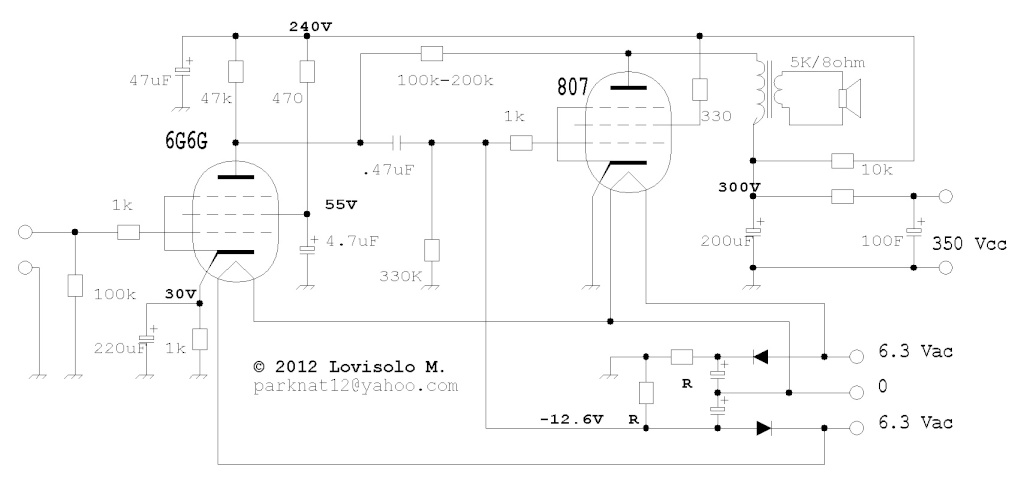
Note: R should be greater than 180k-200k to avoid lowering too much the R-input of the 807
What do you think about my schematic (local feedback and fixed bias for 807)?
Note: R should be greater than 180k-200k to avoid lowering too much the R-input of the 807
Last edited:
The 807 bias needs a few changes:
1. bias resistor should go to bias supply, not ground.
2. bias supply needs some smoothing.
The first stage looks wrong. Should the cathode voltage be 3.0V rather than 30V?
Why use DC heaters? Better to learn how to wire AC heaters.
1. bias resistor should go to bias supply, not ground.
2. bias supply needs some smoothing.
The first stage looks wrong. Should the cathode voltage be 3.0V rather than 30V?
Why use DC heaters? Better to learn how to wire AC heaters.
there is no DC for heaters, heaters are connected directly to the 6.3 Vac.
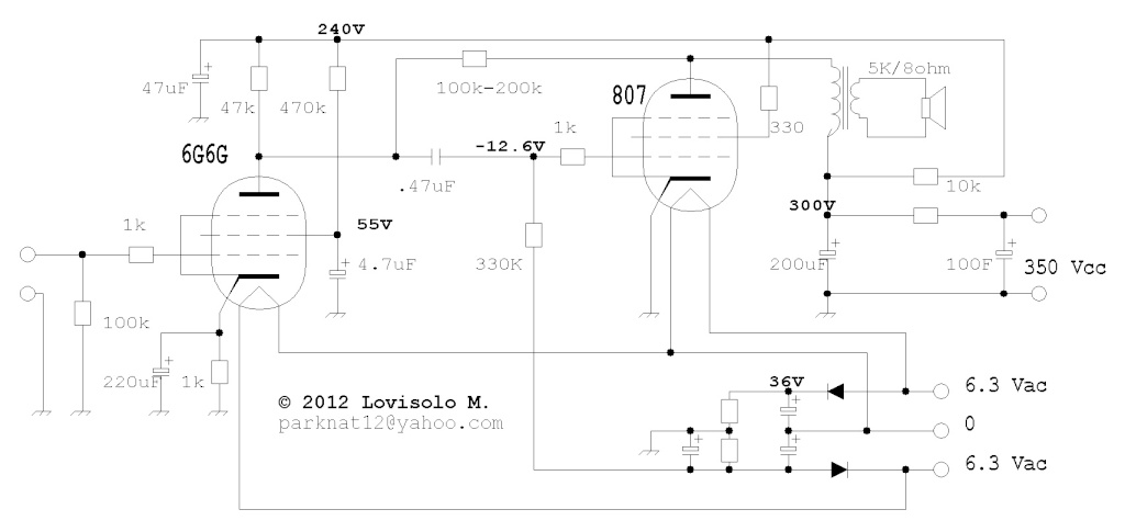
Right, I made a mistake: 6G6V cathode voltage is 3.0V
I should just remove the 330K resistor, I suppose.
Right, I made a mistake: 6G6V cathode voltage is 3.0V
I should just remove the 330K resistor, I suppose.
Last edited:
Taking the bias from the heater winding will give you a hotter dissipation during startup if you have SS HT rectification and no delay.
Small PCB transformer for the bias instead ?
Small PCB transformer for the bias instead ?
Taking the bias from the heater winding will give you a hotter dissipation during startup if you have SS HT rectification and no delay.
Small PCB transformer for the bias instead ?
Good idea! 🙂
No, the 330k resistor needs to be in the bias supply line to grid 1.
You sure abut that 220uF cap bypassing the cathode resistor on the 6G6C?
You sure abut that 220uF cap bypassing the cathode resistor on the 6G6C?
Sorry, my mistake.pilovis said:there is no DC for heaters, heaters are connected directly to the 6.3 Vac.

No, the 330k resistor needs to be in the bias supply line to grid 1.
You sure abut that 220uF cap bypassing the cathode resistor on the 6G6C?
Would be better something like this for biasing the 6G6G ?
If you want more Power, you can go up to 350V on the 807 anode without any problems for 5K load resistance. I tested a few OPs and 350V;5K sounded best. (250V;2.5K was worst)....just my experience
Doesn't matter because you have global feedback. Increase your feedback resistor and the 6G6 load resistance. They form a voltage divider which determines the feedback ratio.
ATM your global amplification is only about ~3
The fact, that this kind of feedback never pleased my ears is another thing....but, well, find that out for yourself 🙂
the 6G6G gain or the total gain?
Doesn't matter because you have global feedback. Increase your feedback resistor and the 6G6 load resistance. They form a voltage divider which determines the feedback ratio.
ATM your global amplification is only about ~3
The fact, that this kind of feedback never pleased my ears is another thing....but, well, find that out for yourself 🙂
Hi This is fun.
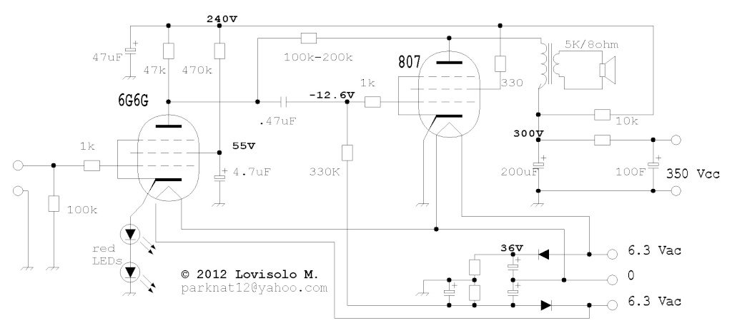
Using tubes way outside their specified operating range. The 807 is OK biased maybe for a little too much plate dissipation - 15V on the grid would be a little kinder to the plate, it is over-dissipating by a bit, but for a big tube like that, it is acceptable. The 6G6 is more troublesome, because it is used way outside its specified range of operation. It is a power pentode used as a low current voltage amplifier. From the RCA book we can estimate that an acceptable operating point for the 6G6 would be about 2mA in the plate and 0.3mA in the screen grid (ratio of 6 to one). All fits the resistor values chosen. An effectively negative grid voltage of 3 volts on the control grid should be proper at 2.3mA the cathode bias resistor should be in the range of 1.2k or there about. Maybe the LEDs would work just fine, but please bypass them with the 220uF cap. I would prefer a 1.2k resistor though.
This amplifier should work just fine and sound good too. It uses negative feedback around the output tube. That lowers the source impedance as seen by the output transformer. Transformers are voltage conveying devices and work best when driven by a low impedance source.
Thank you for the schematic.
Hans J Weedon.
Last edited:
Maybe the LEDs would work just fine, but please bypass them with the 220uF cap
Why ?
That was the reason he used LEDs in the first place - to get rid of the cap. This works great, just be sure to get at least 5mA through them.
There is no way of getting 5mA in the LEDs max 2.5mA, and why get rid of the cap?
I know that caps have a "bad" reputation in audio circuits, but when they are used correctly they are just fine. From my experience a film capacitor versus an electrolytic changed the distortion from 0.001% to 0.0015%, measurable, yes, but not audible under any circumstances.
Hans J Weedon
PS: I have done "high end Audio" stuff for over 60 years by now and I do know what I am talking about.
A bypass cap across the LEDs is superfluous- they might contribute 7 ohms or so impedance, hardly enough to worry about.
Gain from in to the output transformer is about 3, but your output transformer steps things down as well, by a factor of 25. That's a problem.
Gain from in to the output transformer is about 3, but your output transformer steps things down as well, by a factor of 25. That's a problem.
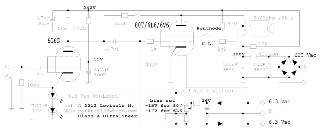
and what about this modified schematic to easily change the output tube just setting the right value for bias voltage?
I like experimenting 🙂
Anyway, I increased the load resistor of 6G6G and the feedback resistor to have a little more gain, also added cap in parallel of the two leds, it may helps.
I like experimenting 🙂
Anyway, I increased the load resistor of 6G6G and the feedback resistor to have a little more gain, also added cap in parallel of the two leds, it may helps.
Last edited:
The cap across the leds ? gives you a little more gain gives a few other IMHO setbacks.
If you´re turning it into a testbed fo swtiching tubes you need variable level of feedback to match the tubetype and mode.
And bias still needs filtering.
If you´re turning it into a testbed fo swtiching tubes you need variable level of feedback to match the tubetype and mode.
And bias still needs filtering.
The cap across the leds ? gives you a little more gain gives a few other IMHO setbacks.
If you´re turning it into a testbed fo swtiching tubes you need variable level of feedback to match the tubetype and mode.
And bias still needs filtering.
Feedback is already variable, please note the pot in series to the other two resistors in the bias line.
Last edited:
The cap across the leds ? gives you a little more gain gives a few other IMHO setbacks.
No, not significantly. The cap can only do bad things there, if it does anything.
- Home
- Amplifiers
- Tubes / Valves
- need help for my new amp: 6G6G driver & 807 SE