The idea can be seen in diagram.
This is only a basic simplyfied schematic. I post in more details later.
Should be noted that these circuits are so far only in my SPICE.
But should work good and give fine performance.
Power chip OPA541 can fead 50 Watt into 8 Ohm.
Max rails are for the chip +/-35 = 70 Volt.
Here I run 6DJ8 and OPA541 at 66 Volt.
Even if OPA541 can amplify voltage, in this case it is used as buffer.
Voltage follower at unity gain.
What come in comes out to speakers.
Distortion is low and can not be perceived as effecting sound.
This means that 6DJ8 totally dominate the distortion, the effects on sound signal.
There are 2 alternative circuits.
One where Triode plateload is resistor, 100kOhm.
One where Triode plateload is a CCS constant current source.
Big difference where CCS gives near hifi performance
and resistor load gives more Triode Tube sound.
Enjoy 🙂
Attachments
Here is Alternative 1.
With resistor 100k as the plateload.
I think this can give Triode Sound as there is a bit distortion.
The output is at least 40 Watt and maybe upto something 50 WAtt.
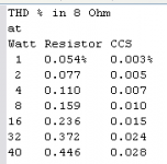
At 1 Watt THD, mostly 2nd harmonic, 0.054%
At 40 Watt 0.446%
The voltage gain is x15.
See figure 1 for a compare THD with Alternative 2. CCS-loaded.
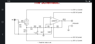
Figure 2 shows the complete circuit of Alt. 1.
With resistor 100k as the plateload.
I think this can give Triode Sound as there is a bit distortion.
The output is at least 40 Watt and maybe upto something 50 WAtt.
At 1 Watt THD, mostly 2nd harmonic, 0.054%
At 40 Watt 0.446%
The voltage gain is x15.
See figure 1 for a compare THD with Alternative 2. CCS-loaded.
Figure 2 shows the complete circuit of Alt. 1.
Attachments

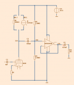
Here is Alternative 2.
With 2 transistors forming a CCS constant current source.
Distortion is low. Near to Hifi!
See figure 1 in previous post for THD figures.
This circuit below, or the one in post above, should be easy to build.
There are few parts and straight foward connections.
Need one transformer 2x24VAC ~200VA to give like 66 Volt DC.
Also some smaller transformer 9 to 12VAC for the heater feeding.
Enjoy 🙂
Attachments

I love this idea. This thread should have been a very popular one, it looks a well conceived amplifier with some very credible advantages.
From what I understand, this is taking the ambience of the triode, and is making that 50 watts of low distortion power with the 541 efficiently with a very simple configuration.
I have had some experience with the 541, I followed a schematic that may have mislead me a bit, it resulted in a very powerful amp, but with lots of distortion and one burnt speaker coil.
Still would like to salvage this build, and maybe do exactly what you have modeled so very professionally. That would just mean adding the ecc88 (I might use a ec83 because that is what I have already) and converting it all point to point.
The circuit board I used for the 541 stereo build was iffy, So will just do it point to point now because why bother with such a simple schematic.
Have you made and listened to one like this before and if so, do you recommend the low distortion schematic?
I like single ended triode, but I dont like all that heat, need for a preamp and 200 watts on the solar array.
Does your schematic allow for a source such as a 3.5mm headphone jack from a phone or dap?
What? Not really. Current is going through a 10k resistor connected to the output and the positive signal input? No that makes no sense. That schematic would not work. Unless you can explain in detail how the speaker negative is conducting through ground.
Please explain opamps to us in more detail, this could be an epic thread.
Or maybe I'll just cut to the chase and suggest you read about how the inverting and non-inverting inputs of the opamp work
Or maybe I'll just cut to the chase and suggest you read about how the inverting and non-inverting inputs of the opamp work
A 6DJ8 cathode follower that is used in its linear range sounds like any triode cathode follower used in its linear range.
There is very little sound variation here.
If you want some 6DJ8 triode sound, then drive the grid, and take the output from the plate.
Various values of B+, plate load resistance, and cathode resistance will allow you to tailor the sound.
Caution:
Watch out for transients at Power-on, Power-off, and during power mains hot-starts. They might take out the power op amp; or one of the speaker drivers, including the woofer, and especially the tweeter. But at the very least, your ears may be offended.
Just my opinions.
Have Fun!
leadbelly. the inputs do not conduct the speaker negative. That is for sure.
The inverting and non inverting inputs do not pertain to the fact the ground in that schematic isnt hooked up to doo.
The inverting and non inverting inputs do not pertain to the fact the ground in that schematic isnt hooked up to doo.
But i dont want to know about THAT schematic, I want to know about the awesome schematic lineup created.
Ah, I see, you don't get that the PS detail isn't shown. That's kind of important, because lineup's schematic just shows the PS as a voltage source, you'll still need to figure out what to build.
So what makes lineup's design awesome is that he used an OPA541 and you already have those?
So what makes lineup's design awesome is that he used an OPA541 and you already have those?
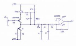
Sort of like this...
M0st of these power OpAmps don’t require extra gain
Just need to take advantage of the cathode follower and invert the OpAmp.
And a CCS at the bottom of the follower really helps as well.
Change the feedback and you can change it to a current amplifier.
dave
True, that's why schematics i attached is using tube as cathode follower, no gain.
But the main reason i posted it was that chip amp is in inverting configuration, signal in is part of feedback. This can not have just volume pot on the input, must have buffer. I built many versions with various jfet buffers, and the sound was way better than recommended application schematics.
But the main reason i posted it was that chip amp is in inverting configuration, signal in is part of feedback. This can not have just volume pot on the input, must have buffer. I built many versions with various jfet buffers, and the sound was way better than recommended application schematics.
But you still cant explain why the inputs carry speaker output current BECAUSE THEY DON'T.
If I want to fry chips, I should follow those last two schematics, believe it will sound better because I'm following a topology that is totally illegitimate, while bellows smoke and hot smoldering opamps ensue.
I mean, If it looked legitimate like lineups schematic, I could comment nicely, but literally those ciruits do not work and are untested and unproven.
- Home
- Amplifiers
- Tubes / Valves
- Listen to 6DJ8 Triode through Power Chip IC. Easy project.