Hallo ,
i have 2 output transformers from ROWE AMI MM4
I do not know how to get sekundar output
this color ist:
Black
brown-white
white
yellow
green
green-white
green-yellow
i have 2 output transformers from ROWE AMI MM4
I do not know how to get sekundar output
this color ist:
Black
brown-white
white
yellow
green
green-white
green-yellow
Cathode Feedback
Resurrecting an old thread.
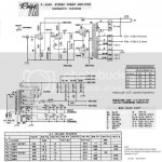
The Ami Rowe output transformers are designed for many complex speaker arrangements, but they do cope quite nicely with being used for two speakers in stereo.
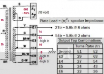
If you look at the picture below, there is also a 70v winding for speakers using line output transformers. It is centre tapped, so presumably that would mean 35v on each side of the CT.
Since the B+ is 365v, doesn't that mean that that line output winding could be used as a Cathode FB winding, with 10% feedback for each tube?
Resurrecting an old thread.
The Ami Rowe output transformers are designed for many complex speaker arrangements, but they do cope quite nicely with being used for two speakers in stereo.
If you look at the picture below, there is also a 70v winding for speakers using line output transformers. It is centre tapped, so presumably that would mean 35v on each side of the CT.
Since the B+ is 365v, doesn't that mean that that line output winding could be used as a Cathode FB winding, with 10% feedback for each tube?
Attachments
Yes and no. You certainly could use this winding for cathode feedback, but feedback ratio is assigned with turns ratio rather than output to supply voltage ratio.
Best regards!
Best regards!
Hi Kay, just to be sure, to calculate the turns ratio, I would need to put an AC voltage, say 100V across the primary, and measure the voltage across the 70v line level output winding? And since both windings are centre-tapped, the turns ration is the same for each half winding (primary to secondary)?
And if I record 10VAC on the secondary winding, with 100VAC on the primary, then I have the equivalent of a 10%CFB winding?
Cheers, Richard
And if I record 10VAC on the secondary winding, with 100VAC on the primary, then I have the equivalent of a 10%CFB winding?
Cheers, Richard
...........used as a Cathode FB winding, with 10% feedback for each tube?
The 70V CT is 35V each side, so 49V peak each end of the winding.
The power stage grid-cathode bias is 18.5V, and that is probably the peak grid signal voltage.
Add half the 70V winding to that, we now need 68V peak each grid. 11dB of NFB, and a LOT to ask of a driver. (The 353V cathodyne here won't come close.)
And remember that the additional cathode winding will increase the finals' load impedance, which might turn into decreased output power.
Best regards!
Best regards!
Ok, so I hope I am getting it now.
It is conceptually feasible to utilise the seperate winding for cathode feedback, but the new design would require a new driver choice (probably two stages by the sound of it), and potentially a new operating point for the finals, to retain the same load impedance.
I.e. a new amplifier! ;-)
Thanks for the help!
It's about 30W, but more simple from the supply voltage.Yes, but we need to know the power output to calculate the 70 V winding's turns.
Best regards!
365V minus voltage drop on DC-resistance (15V) minus bottom anode voltage (50V) give a swing of 300V.The 70V out is ~100V peak.So from 300 to 100V gives 70V winding x3 turns = half primary winding.
Mona
@huggygood are you in the same position as me?
I have two Ami Rowe amps now. One is converted to 6L6GT and has a substitute power traffo, the other is original with 7868s. Apart from the 70VCT output winding, there are also some very nice alternate combinations of the secondary windings, giving a great range of reflected impedances.

It would be nice to do something novel with one pair of the OPTs. I was thinking along the lines of a sweep tube like EL36, in ultralinear using the tertiary winding for the screens, and the lowest secondary impedance. Or 12E1 possibly, a series pass tube with a low screen voltage requirement.
Anyone with a novel idea? I have plenty of tube options.
I have two Ami Rowe amps now. One is converted to 6L6GT and has a substitute power traffo, the other is original with 7868s. Apart from the 70VCT output winding, there are also some very nice alternate combinations of the secondary windings, giving a great range of reflected impedances.
It would be nice to do something novel with one pair of the OPTs. I was thinking along the lines of a sweep tube like EL36, in ultralinear using the tertiary winding for the screens, and the lowest secondary impedance. Or 12E1 possibly, a series pass tube with a low screen voltage requirement.
Anyone with a novel idea? I have plenty of tube options.
I myself noted some combinations of windings but without the 70v, I did not even think of it in reality.
the amp that uses the 6p3-se is now based on a Harman A300 schematic but cathode biased, the 7591 is an Ami-Rowe schematic and I also have a lot of tubes that would go well with these OPTs.
the amp that uses the 6p3-se is now based on a Harman A300 schematic but cathode biased, the 7591 is an Ami-Rowe schematic and I also have a lot of tubes that would go well with these OPTs.
- Home
- Amplifiers
- Tubes / Valves
- Output transformer from rowe ammi mm4