Hi to all,
Because of the big success of the I/V SRPP Tube Stage in my finished 4x TDA1541A DAC,
i am planning a PCB Group Buy for those who want to have a optical and technical perfect solution (minimum pre-order 20 PCB´s).
This PCB is for "I-OUT" DAC´s with unbalanced output.
If you want to use it with a "V-OUT" DAC, you must insert a capacitor between the DAC and the PCB.
I have added my Heater-Switch Circuit to the PCB.
Now everyone is able to change between the Russian (6N1P, 6N2P ect.) and Western (12AX7, ECC83 ect.) pinout, without soldering.
The Anode and Heater PSU is included.
There will be the possibility to use an external Anode-PSU, e.g. for upgrading with a Tube rectifier.
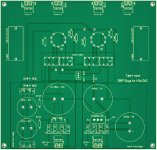
Furthermore i made the Audio-Lines extra wide (1,5mm) and choose 70µm copper to get minimal loss.
It will be a 2-Layer Design to seaprate the Audio-Lines (Bottom Layer) from the Electrical-Lines (Top-Layer).
The new Tube-I-zator V3.1
The evolution brings the following changes:
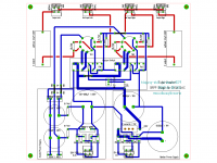
- Anode PSU with Salas SSHV Shunt Reg. onboard
- External B+ Input for usage with other Anode PSU
- Heater PSU with C-R-C filtering
- Heater PSU with Softstart circuit
- Heater PSU Power LED
- Design failures corrected
Thanks to John (-ecdesigns-) for the following suggestions!
- Grid stoppers to prevent unwanted oscillations
- Bias current injection for TDA1541A usage
- Pull-down resistors to keep the coupling cap output at GND-potential
Still on the Module:
- Heater switch for 6N2P or 12AX7 usage
New version 3
You will find the BOM in my blog HERE!
For orders please send me a PM or a mail to diyaudiopcb (at) gmx.com
Best regards to the community
dvb-projekt

Because of the big success of the I/V SRPP Tube Stage in my finished 4x TDA1541A DAC,
i am planning a PCB Group Buy for those who want to have a optical and technical perfect solution (minimum pre-order 20 PCB´s).
This PCB is for "I-OUT" DAC´s with unbalanced output.
If you want to use it with a "V-OUT" DAC, you must insert a capacitor between the DAC and the PCB.
I have added my Heater-Switch Circuit to the PCB.
Now everyone is able to change between the Russian (6N1P, 6N2P ect.) and Western (12AX7, ECC83 ect.) pinout, without soldering.
The Anode and Heater PSU is included.
There will be the possibility to use an external Anode-PSU, e.g. for upgrading with a Tube rectifier.
Furthermore i made the Audio-Lines extra wide (1,5mm) and choose 70µm copper to get minimal loss.
It will be a 2-Layer Design to seaprate the Audio-Lines (Bottom Layer) from the Electrical-Lines (Top-Layer).
The new Tube-I-zator V3.1
The evolution brings the following changes:
- Anode PSU with Salas SSHV Shunt Reg. onboard
- External B+ Input for usage with other Anode PSU
- Heater PSU with C-R-C filtering
- Heater PSU with Softstart circuit
- Heater PSU Power LED
- Design failures corrected
Thanks to John (-ecdesigns-) for the following suggestions!
- Grid stoppers to prevent unwanted oscillations
- Bias current injection for TDA1541A usage
- Pull-down resistors to keep the coupling cap output at GND-potential
Still on the Module:
- Heater switch for 6N2P or 12AX7 usage
New version 3
You will find the BOM in my blog HERE!
For orders please send me a PM or a mail to diyaudiopcb (at) gmx.com
Best regards to the community
dvb-projekt
Attachments
Last edited:
Please don´t forget to write your location in the pre-order, because of the shipping costs.

Last edited:
schematic
I like to order but don't you think that usd 32 Is too high
If you are not willing to pay it, then I guess it is 🙂
schematic
I like to order but don't you think that usd 32 Is too high
Fell free to save $27 plus the $5 donation to diyAudio and make your own PCB.

do you provide building guides for voltage out and current output dac for this board and some guides for the BOM...?
do you provide building guides for voltage out and current output dac for this board and some guides for the BOM...?
The parts you will need are all standard parts and are depending of the DAC and tubes you will use.
If i should give a recommendation:
Rectifier Diodes: Fairchild Stelth ISL9R460PF2 (Mouser Part-No: 512-ISL9R460PF2)
Resistors: Texas Components TX2575 (Texas Components - Precision Resistor & Microelectronics)
Tubes: Russian 6N2P-ER or the brand new E813CC from TechTube (www.techtubevalves.com)
If you will have additional questions, feel free to send a PM.
I will try my best to share my experiences.
Best regards,
Oliver[/FONT]
would you post schematic
have you tried mu follower
In my DAC projekt i have made only the SRPP-Stage.
Best,
Oliver
I will be interested in 3 boards. I am in the US. Thanks.
Hi toufu,
please place your pre-order on lzpcb@gmx.com
Thanks,
Oliver
I've got pcb's for the lightspeed from dvb-projekt . Very good quality. But in this case. If you find it too expensive. Best would be to go p2p. It is quite a simple circuit.I like to order but don't you think that usd 32 Is too high
Kind regards,
Bas
I've got pcb's for the lightspeed from dvb-projekt . Very good quality. But in this case. If you find it too expensive. Best would be to go p2p. It is quite a simple circuit.
Kind regards,
Bas
That would be the other option

 We will lock temporarily the thread. It is ''Under investigation''.
EDIT: The thread is back in operation after the disputed buzzword and other references have been removed or substituted both from thread's title, text, and PCBs. Please refer any technical question only to the group buy manager.
An externally hosted image should be here but it was not working when we last tested it.
This tube SRPP buffer cost $ 30,- incl. all parts and is ready build.
I like it very much. This posting i made because there are already a lot of srpp tube buffers to buy.
Like these:
Pre - AMP Peramplifier KIT Tube 6N11 SRPP for DIY - eBay, Integrated Amplifiers, Amplifiers, Home Audio, Electronics. (Eindtijd 15-dec-09 10:28:13 CET)
High End Class A tube buffer 6DJ8/6922/6N11 assembled - eBay, Integrated Amplifiers, Amplifiers, Home Audio, Electronics. (Eindtijd 10-jan-10 09:00:26 CET)
The output impedance of this circuit is?
Thanks
Here is a little excel application where you can calculate the output impedance of several tubes in a srpp stage.
http://www.ict-net.net/tube.xls
Last edited:
Hi Koifarm,
thank´s for your post. I think everyone know this, because that´s nothing new.
The most advantage of the Tube-I-zator board is that you are not fixed to any 9-Pin tube,
because of the Heater-Switch. As i know the community, they would like to test the
circuit with different tubes in their projects.
The link to the excel application is pretty cool. Perhaps you could also post it to the....
Ups, i see you already made it. Thanks.
- Home
- Group Buys
- Tube-I-zator Professional PCB