Hugo, you can order the service manual from Lange for 12 euro's or so.
http://www.schaltungsdienst.de/index.php?id=22
Jan
http://www.schaltungsdienst.de/index.php?id=22
Jan
I changed the thread title a bit to give this post more sense.
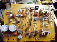
Left top TR01 most likely a current source for the dual Jfet (FET01) diff pair below it.
Middle, eight transistors (TR02-09), not sure what they are doing.
Next TR10, TR11, D03, D04 which would be the bias circuit.
TR12, TR14 pre drivers and TR13, TR15, drivers.
When the amp came in, two of the four NMA1012 were broken as well as a 2SC2238 driver (TR13). I replaced the outputs with MJ21193 and the driver with MJE15032.
A bad soldered cap is most likely the culprit. (Base to collector cap of TR12)
Now, without outputs connected, the emitter R of TR11 went up in smoke.
TR11 is still fine.
I replace the R and can’t measure any ohmic difference between both channels.
All transistors, diodes and resistors seem fine, still TR11 is heating up quickly when I power up with the variac. Vbe, however, is higher (0.7V and up) compared with the other channel, a steady +/-0.6V.
/Hugo
Attachments
That's extremely close except for the output (complementary instead of quasi), which is not important.
Thanks, thanks, thanks...and thanks 🙂
/Hugo
Thanks, thanks, thanks...and thanks 🙂
/Hugo
Netlist said:
Middle, eight transistors (TR02-09), not sure what they are doing.
Heh, which probably means you should find out before continuing to poke around the amp! 🙂
The BA-F1 uses Sansui's DD-DC setup, basics go like this:
1st stage is a FET follower (IIRC... it might be a differential).
2nd stage is a commplementary LTP with tails tied one into the other. The collectors are cascoded (hence 8 transistors total). Because you need a voltage difference between the emitters of the LTPs to get tail current, the bases of the PNP and NPN LTP are separated by a tripple or quadrupple diode (I think tripple in the BA-F1), that is fed by stage 1.
3rd stage is a complementary VAS, with Vbe multiplir for output stage bias.
4th, 5th, 6th stage are a tripple darlington arrangement.
This is from memory so don't take it literally, but you should be able to follow the circuit using this basic template. IIRC the BA-F1 is, circuit-evolution-wise, between the AU919 which quietly introduced a version of the DD-DC circuit, and the AU-X1, and then the latter AU-D9/11 which introduced feedforward.
Hi Hugo,
I didn't get a notification on your's or ilimzn's posts. I'm very happy that it helped.
Hi ilimzn,
I sent Hugo some poor copy of the AU-919 from looking at the board and checking some clues he mentioned. You description works right in then.
-Chris
I didn't get a notification on your's or ilimzn's posts. I'm very happy that it helped.
Hi ilimzn,
I sent Hugo some poor copy of the AU-919 from looking at the board and checking some clues he mentioned. You description works right in then.
-Chris
SM on the way to you Hugo, through USendIt. Let me know if you do not get the link.
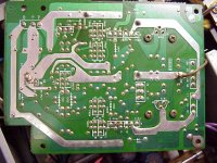
Edit: Here's the driver board so everyone else can see.
Edit: Here's the driver board so everyone else can see.
An externally hosted image should be here but it was not working when we last tested it.
Here's the other channel driver, where Sansui shows the voltages.
An externally hosted image should be here but it was not working when we last tested it.
I dunno what others think, but I rank the BA-F1 as one of the top 5 solid-state amps I've ever listened to, as long as it still has the original output devices.
Thanks to all. After some more coffee, I'll sharpen my measuring pens and get back to you in a while.
Nothing fixed yet, it was too late yesterday.
Interesting post on the output devices. I'll compare the one channel (originals) with the MJ21193 channel ones it plays.
/Hugo
Nothing fixed yet, it was too late yesterday.
Interesting post on the output devices. I'll compare the one channel (originals) with the MJ21193 channel ones it plays.
/Hugo
Yes, perfect manual.
I just started measuring and found odd voltages in the bias circuit.
With half the supply voltage of 56 and -56V (27v and -27V) I get -14V on collector of TR10 and -20V on collector of TR11.
/Hugo
I just started measuring and found odd voltages in the bias circuit.
With half the supply voltage of 56 and -56V (27v and -27V) I get -14V on collector of TR10 and -20V on collector of TR11.
/Hugo
EchoWars said:Hugo...
Were you able to download the manual from the link I gave?
can you share a link with rest of greedy boyz?

edit:
never mind, I just realize that Yousendit is sorta PtP ?
- Home
- Amplifiers
- Solid State
- Faulty Sansui BA-F1 could use some help