When I engage the Bass Contour or loudness contour switch the unit hums in both channels, even with the volume all the way down.
When the Loudness is off unit does not hum, even at full volume. This amp has special Harmon Kardon Phase Correction Loudness.
Is there an area on this high power integrated amp I need to look. Perhaps the part of the power supply that the loudness circuit gets its juice from?
When the Loudness is off unit does not hum, even at full volume. This amp has special Harmon Kardon Phase Correction Loudness.
Is there an area on this high power integrated amp I need to look. Perhaps the part of the power supply that the loudness circuit gets its juice from?
PM665 Hum
Has anyone found a cure for the bass countour hum problem, I have one that I recaped an still has it.
Has anyone found a cure for the bass countour hum problem, I have one that I recaped an still has it.
Don't use it, it's the worst circuit in the amp and it will influence the original good sounding, so just use the volume only.
Don't use it, it's the worst circuit in the amp and it will influence the original good sounding, so just use the volume only.
The 'Bass Contour' is a loudness control circuit boost the 50Hz, it is not a hi-fi designed circuit, so that using it will influence the original amp good sounding. Better just using the volume and tone controls to set your comfort listening level.
I think we've discussed this loudness circuit before; other models like the PM-655 and PM-645 also have it. It is a thoroughly anachronistic design for a late-'80s amp with basically zero inherent PSRR, and supplied from the main power rails with a single transistor zener follower regulator (while noise levels would be low, you can expect maybe 50 dB of PSRR from that). Hum levels presumably were marginal from day one.
I can think of a million different ways of addressing the issues - the question is how much of a project do you want this to be? I am pretty confident that it shouldn't take more than a few electrolytic caps, resistors and some wire for a substantial improvement across the board. You could also rip it out and replace it with an opamp-based contraption though, or add some sort of pre-regulator, or...
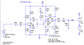
It doesn't look like I've ever simulated the circuit. It's not too complex, so that would be step one.
As expected, PSRR of the actual circuit is Not Good. At 100 Hz, +PSRR = ~4 dB, -PSRR = -1 dB (!). Our biggest problem is the first stage, but the second stage is little more than 6 dB better. Oh boy.It doesn't look like I've ever simulated the circuit. It's not too complex, so that would be step one.
I'll have to play around with this for a bit...
Attachments
First draft for a mod.
Before....

and after:

Looks a bit hacked up, but both +PSRR and -PSRR are now comfortably above 40 dB at 100 Hz. (Wideband is much better, too.)
I used the COM symbol for power ground for the capacitors to be added; this is supposed to run alongside V+ and V- back to the regulator area, maybe ground at C63/C64. I would not trust local signal ground for this. Use wires of a half-decent cross-section. Capacitors can be any good general purpose type with low leakage current (e.g. Panasonic FM, FC).
BTW, I was mistaken about the function of Q901 earlier; it appears to be an allpass.
Before....
and after:
Looks a bit hacked up, but both +PSRR and -PSRR are now comfortably above 40 dB at 100 Hz. (Wideband is much better, too.)
I used the COM symbol for power ground for the capacitors to be added; this is supposed to run alongside V+ and V- back to the regulator area, maybe ground at C63/C64. I would not trust local signal ground for this. Use wires of a half-decent cross-section. Capacitors can be any good general purpose type with low leakage current (e.g. Panasonic FM, FC).
BTW, I was mistaken about the function of Q901 earlier; it appears to be an allpass.
Attachments
Last edited:
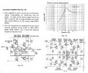
Here is a Sony Pro series preamp low-boost circuit for reference.
But when compare with the phone amp , buffer amp and line amp which using a lot of expensive twin input fets and twin transistors in their circuit, using this simple discrete low-boost amp circuit seems downgrade the whole preamp performance.
But when compare with the phone amp , buffer amp and line amp which using a lot of expensive twin input fets and twin transistors in their circuit, using this simple discrete low-boost amp circuit seems downgrade the whole preamp performance.
Attachments
Last edited:
- Home
- Amplifiers
- Solid State
- hum in harmon kardon pm665


