I have an F5 with Toshiba laterals. I have the source on the power lines now; however, with my Maggie at 4Ω it is rather too harsh sounding. So back to some source degradation.
What do you think of the following development path? [I used to have such a version with the source resistors and it sounded good actually so after some years I am thinking of 'going back'.]

The difference with my 'standard F5 build' is the drain resistors and the fad of the 3Farad capacitor. In fact, that forces a nice harmonic degradation on paper.
What do you think of the following development path? [I used to have such a version with the source resistors and it sounded good actually so after some years I am thinking of 'going back'.]
The difference with my 'standard F5 build' is the drain resistors and the fad of the 3Farad capacitor. In fact, that forces a nice harmonic degradation on paper.
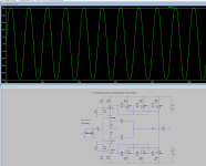
Attachments

Can a single JFET like the 170/74s drive four lateral FETs? That seems like a lot of capacitance. I could be wrong.
Triode_Al
I have drawn out a Turbo F5 Lateral Mosfet amp. Haven't built it yet but gathering parts and hopefully a friend will help with the P-Spice modelling. Have included it below. The Toshiba's aren't lateral mosfets by the way, although your diagram has Hitachi's which are lateral. Anyway, hoping Nelson will show us his F5 Lateral version he has been promising for a long time.....

I have drawn out a Turbo F5 Lateral Mosfet amp. Haven't built it yet but gathering parts and hopefully a friend will help with the P-Spice modelling. Have included it below. The Toshiba's aren't lateral mosfets by the way, although your diagram has Hitachi's which are lateral. Anyway, hoping Nelson will show us his F5 Lateral version he has been promising for a long time.....
Looks good, Ejam. I like the cascode.
It does have the possibility to reduce the effect of the Miller capacitance on the input FETs if I am correct (the gate chages of the output reflected to the input). Then it drives the four gates better? Well, as I see it four degenerated laterals have less dynamic input capacity problem as one standard power mosfet. Note 'see': I have no way to test.
& Soundchaser: With two laterals without degeneration and a bare input (no cascode) input FET I currently have a bandwidth of 5 MEGAherz.
Beyond that, the cascode gves the capability to set the input FETs in a region where they are "less lineair": look at it as the H2-generator built into this topology. That imples then: very well studied bias of that stage. (Like Hiraga did, setting it at 6V - implying that R6/R8 could be lowered with some positive effect.) It would only help if the two could be varied in situ live while looking at an analog distortionmeter.
I think the R3/R4 can be a 20 ohm pot. A good one . . maybe multiturn is overkill. I use it to finetune the output DC in my Hiraga LeMonstre.
- 'Strange' that the Gm Transconductance is thrown away, not for matching but also to increase the output impedance and reduce the loop gain . . . quite the opposite strategy of old times with them BIG Threshold amplifiers. 😕
Sir, not to hijack your thread, but I'm thinking of doing perhaps something similar with F5m. I intend to soon have some ECW20N/P20 Exicons, i know these are for big amps, but I just want to try. Would you be kind enough, to briefly describe the changes I need to do or to pay attention to when changing to these MOSFETs? I mean is it interchangeable and the same circuit would actually work? Or work but not optimally? Or not work at all? If you'd give me a few pointers to newbz, where to pay attention - it would be much appreciated.
Hotep
Two suggestions, firstly reduce the gate resistors to 330R on the n-channel and 180R on the p-channel, also reduce the source resistors to 0R22. May need to experiment with values but should be in the ball park. Secondly reduce the mosfet pairs to either one or two for the 20N20/20P20 mosfets. Two pair is the limit for the front end cascode. If using one pair keep the bias current at 1.5A, if two raise to 2A, you'll again have to find what is the best sound.
Contrary to popular wisdom, with laterals more current does not give better sound. When listening (given my particular system and tastes) biasing above 500mA per 10N20 or 10P20 mosfets does not change the sound quality and leads to greater challenges with the heat generated and in some cases the sound takes on a vagueness. Using double die fets, I can't say with certainty if this observation holds but I would start at 500mA and increase till you hear no change. Common sense would say, 1A being double, but the packaging is not double the size, and so down the rabbit hole we go. I know one thing, find the biggest heatsink, say 5U size, then you can experiment with biasing up to 1A per device (4 devices at 1A with 32V rails on a 0.25W/deg heatsink gives a raise of 32degrees). Just good enough for 20degree ambient (52degrees), not so good in the tropics at 30degrees ambient (62degrees). Break out the fan cooling.
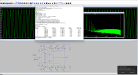
Have included some P-Spice modelling a friend of mine did for me. He suggested 220pF compensation caps, if me I would place them in parallel with the 50ohm feedback resistors.
Hope this helps
Two suggestions, firstly reduce the gate resistors to 330R on the n-channel and 180R on the p-channel, also reduce the source resistors to 0R22. May need to experiment with values but should be in the ball park. Secondly reduce the mosfet pairs to either one or two for the 20N20/20P20 mosfets. Two pair is the limit for the front end cascode. If using one pair keep the bias current at 1.5A, if two raise to 2A, you'll again have to find what is the best sound.
Contrary to popular wisdom, with laterals more current does not give better sound. When listening (given my particular system and tastes) biasing above 500mA per 10N20 or 10P20 mosfets does not change the sound quality and leads to greater challenges with the heat generated and in some cases the sound takes on a vagueness. Using double die fets, I can't say with certainty if this observation holds but I would start at 500mA and increase till you hear no change. Common sense would say, 1A being double, but the packaging is not double the size, and so down the rabbit hole we go. I know one thing, find the biggest heatsink, say 5U size, then you can experiment with biasing up to 1A per device (4 devices at 1A with 32V rails on a 0.25W/deg heatsink gives a raise of 32degrees). Just good enough for 20degree ambient (52degrees), not so good in the tropics at 30degrees ambient (62degrees). Break out the fan cooling.
Have included some P-Spice modelling a friend of mine did for me. He suggested 220pF compensation caps, if me I would place them in parallel with the 50ohm feedback resistors.
Hope this helps
Attachments

To be fair I intend to assemble F5M for starters, see if I like the sound at all. Then go from there. My rails will be either 17 or ~ 33Vdc. This is just an experiment, I don't know if I'll put in significant brain power and the resources into it. Just want to play around. I will only use one mosfet pair of course. For starters at least. You guys here are doing more advanced stuff than I intend to.Two suggestions, firstly reduce the gate resistors to 330R on the n-channel and 180R on the p-channel, also reduce the source resistors to 0R22. May need to experiment with values but should be in the ball park. Secondly reduce the mosfet pairs to either one or two for the 20N20/20P20 mosfets. Two pair is the limit for the front end cascode. If using one pair keep the bias current at 1.5A, if two raise to 2A, you'll again have to find what is the best sound.
The reduction works out well. You can check - that the threshold of the laterals is less than the mosfets. Anyway, do an initial setup before powering up (dial potmeters for current flow to 0 well at least direction zero first).reduce the source resistors to 0R22
As current thoughts
 I agree with Ejam.
I want to reduce the number of stages as much as possible. So I won't do cascode. After I get the basic F5m running, I think I'll try to implement something like in your original post. Although I don't understand C8 or what it does. Or where you can even find 3F caps.With two laterals without degeneration and a bare input (no cascode) input FET I currently have a bandwidth of 5 MEGAherz.
I guess I'll start where you are thinking of going back. In other words, do something more standard, don't fiddle with drain resistors, but it would be nice to just copy your schematic for a single pair of 20N20/20P20. I have J55 K175 too BTW, but I don't know if they're still alive. I could compare the sound if they are indeed alive.[I used to have such a version with the source resistors and it sounded good actually so after some years I am thinking of 'going back'.]
On the other hand if it's a cascode maybe I'm fearing unnecessarily. But is there really any benefit? Especially with single pair of 20N20/20P20? I don't need pretty distortion necessarily, I want maximum purity.
Hotep
Regarding the use of a cascode front end, I use it because my proposed amp has 32V rails and just to be on the safe side I cascode to reduce the voltage drop across the jfet. Toshiba jfets have a limit of 40V source-drain so you could use them non-cascode as Nelson did in the F5 Tubro V1 and V2. Linear Systems jfets, I'm not so sure.
I think it is a good idea to start off with one pair of 20N20/20P20, then add when you have a working amp. Make sure you use ceramic (aluminium oxide) pads to prevent instability issues with capacitance between the mosfet case and the heatsink.
Hope this helps and good luck.
Oh, I didn't know there was an issue of capacitance with the heatsink. Thanks. I have even better pads, around 5 or 10 times better thermal conductivity I think. They are aluminum nitride.Make sure you use ceramic (aluminium oxide) pads
I think my rails are gonna be around 30V but I don't know yet exactly.
I also use the AlO2 insulation. The 20N20 is double-die, so twice, well matched inside. One should be enough as a starter.
I am a bit lost as to why you chose laterals to Toshiba.
You said it couldn't drive your 4 ohm speakers properly.
But you choose to use another device with only 1/3 of the transconductance.
What is the logic behind that ?
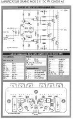
We have built a Class AB amp based on the Grandmos, with 2 pairs of double die matched Exicons per channel.
In this case, the laterals are used as followers, and the F5 with TO220 as VAS.
The negative feedback will reduce the output impedance of the laterals.
And the open loop gain is determined by the front end.
The frontend and the follower no longer have to share the same power supply.
And of could for 4 ohm, you can reduce the voltage, as you need more current instead.
Just my 2 cents,
Patrick
.
You said it couldn't drive your 4 ohm speakers properly.
But you choose to use another device with only 1/3 of the transconductance.
What is the logic behind that ?
We have built a Class AB amp based on the Grandmos, with 2 pairs of double die matched Exicons per channel.
In this case, the laterals are used as followers, and the F5 with TO220 as VAS.
The negative feedback will reduce the output impedance of the laterals.
And the open loop gain is determined by the front end.
The frontend and the follower no longer have to share the same power supply.
And of could for 4 ohm, you can reduce the voltage, as you need more current instead.
Just my 2 cents,
Patrick
.
Attachments
Last edited:
A couple more links.
I think Juma's (1st link) will fit what you want.
You can still consider using 2pairs of double due Exicon's, and reduce source resistor to 0.1R per FET.
www.diyaudio.com/community/threads/f5-meets-buzquito.162042/
www.diyaudio.com/community/threads/pass-f5m.406472/post-7592575
www.diyaudio.com/community/threads/pass-f5m.406472/post-7592443
www.diyaudio.com/community/threads/pass-f5m.406472/post-7592491
Patrick
Last edited:
Patrick
Trouble is Toshiba stopped production many years ago and getting them is very difficult nowadays (let alone at a reasonable price), and given the multitude of fakes from the PRC. I'm sure you have a workshop full of them and good luck to you. Hell, I'm envious. For the rest of us, Exicon is the go, despite their transconductance limitations. I think the double die version is more than acceptable, having built a 100W Class AB amp using them. Now if you'd care to share your Grandmos variation we'd be all eternally grateful and it would be a good counterpoint to Nelson's soon to be released lateral F5 creation.
P.S. Don't you love autocorrect turning Grandmos into Grandma's, I had to go back three times to correct it and it keep changing back.
Patrick
Found your creation in your fourth link, nice. Can you suggest a substitute for those Toshiba drivers, another out of production years ago mosfet.
Found your creation in your fourth link, nice. Can you suggest a substitute for those Toshiba drivers, another out of production years ago mosfet.
- Patrick, I bought a stash of these 2sk175 + 2SJ55 Toshiba's when I worked in Canton.
Great. Bien conçu.
Same happened to me.P.S. Don't you love autocorrect turning Grandmos into Grandma's, I had to go back three times to correct it and it keep changing back.
Double die Exicon is 14€+VAT per piece.For the rest of us, Exicon is the go, despite their transconductance limitations. I think the double die version is more than acceptable ...
You need at least two to come close to Toshiba.
Selected (vgs matched) version costs more, and only on request.
I also use Exicons, for a different reason.
Wait for the F5XL, hopefully end of 2025.
Patrick
- Home
- Amplifiers
- Pass Labs
- An F5 with laterals