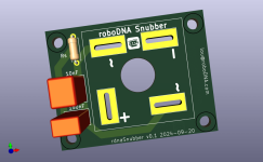
Here is the gerber zip for my rectifier daughterboard. It's not tested yet but feel free to try it if you are brave. Using the gerber, you can get them made at PCB houses like JLCPCB for a couple of dollars for 5 PCBs.
After @birdbox and I test them, I'll post an updated version or version1.0 if nothing changes.
UPDATE Version0.3 - Made center hole larger. Removed rectifier pads from bottom of board. Moved resistor and caps further from rectifier.
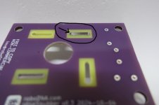
NOTE: I used 2 toothpicks between the rectifier and board to ensure the case does not come close to the 2 rectifier tab holes which have a copper pad on the top later, and a copper hole. ( there are no copper pads on the bottom for any of the 4 holes ) I raised the rectifier off the board slightly since there is a small chance the manufacturing process may result in the copper holes extending above the PCB surface and making contact with the rectifier case. I doubt that would ever happen and I can't see the rectifier case ever reaching those areas, but still raised it off the board a bit. The other 2 holes ( + and - ) have no copper pads or holes so those would never be a shorting risk.
NOTE2: I included an image to show how the hole's copper may extend above the surface of the PCB. If the rectifier case is flush to the board, it possibly can slide too close to these copper holes ( within a couple of mm ) so use 2 toothpicks to raise the rectifier above the board. It depends on how the rectifier is manufactured, and some rectifiers could potentially have a greater offset than others.

After @birdbox and I test them, I'll post an updated version or version1.0 if nothing changes.
UPDATE Version0.3 - Made center hole larger. Removed rectifier pads from bottom of board. Moved resistor and caps further from rectifier.
NOTE: I used 2 toothpicks between the rectifier and board to ensure the case does not come close to the 2 rectifier tab holes which have a copper pad on the top later, and a copper hole. ( there are no copper pads on the bottom for any of the 4 holes ) I raised the rectifier off the board slightly since there is a small chance the manufacturing process may result in the copper holes extending above the PCB surface and making contact with the rectifier case. I doubt that would ever happen and I can't see the rectifier case ever reaching those areas, but still raised it off the board a bit. The other 2 holes ( + and - ) have no copper pads or holes so those would never be a shorting risk.
NOTE2: I included an image to show how the hole's copper may extend above the surface of the PCB. If the rectifier case is flush to the board, it possibly can slide too close to these copper holes ( within a couple of mm ) so use 2 toothpicks to raise the rectifier above the board. It depends on how the rectifier is manufactured, and some rectifiers could potentially have a greater offset than others.
Attachments
Last edited:

I also saw the one someone posted on Etsy. I originally create one with screw headers, not realizing I could just use spade connectors directly to the rectifier. We somehow wound up with different footprints for the 2 capacitors... I used the datasheet for my sizes but have not ordered caps yet to see if they fit. I'm 100% sure they are 5mm pitch though which we both have. Your resistor footprint looks larger too... I went with 7.3mm length for the resistor. ( that is how I was able to fit the resistor and 2 caps vertically ) I also used thin holes to hopefully make it a bit easier to solder but not sure that will help much. I did not want to make the pads too large for that reason. I see the white silkscreen spot you used to write in the resistor value... a VM is required for mine 😉
I changed the nomenclature to Cs for serial cap, and Cx for parallel cap. ( will wait for other tweaks before posting update to version0.1 )
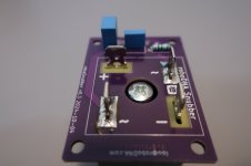
I made a first attempt at using my snubber board. Not sure why I used a larger footprint for the Cx cap. I thought the datasheet showed that size. No big deal. Does this look ok? I used the following parts:
0.15uF 250V 5% Mouser 871-B32529C3154K189
10nF 250V 5% Mouser 871-B32529C3103J189
20ohm 1% 1/4 Mouser 708-RNF14FTD20R0
0.15uF 250V 5% Mouser 871-B32529C3154K189
10nF 250V 5% Mouser 871-B32529C3103J189
20ohm 1% 1/4 Mouser 708-RNF14FTD20R0
Attachments
Version0.3 seems to work ok for me. If anyone else is brave enough test it or has used it let me know how it went and if it's all good. I'll change the version number to 1.0 once it's been used successfully for some time by more than 1 builder ( me so far ).
Hey all a couple of questions!
1. Any reason the pcb design is using "supported dilled slots" for the bolt and not just cutting that out in the creation? Is that because the bolt size changes depending on the rectifier or something?
2. I uploaded to oshpark. Looks like its ~13 for 3 of them. Do I want 2oz copper or just take the default? ( I'm not even sure what that is! ). When I select it there is no change in price - worth it?
Also curious if there are recommendations on a pcb manufacturer for this in the us beyond oshpark - just curious. I've ordered from them in the past and. been very satisfied.
Also what are folks using for the DC side on this? Are people using the dc side of universal power pcb? I'm going to be using this for an M2x build. I sorta have things together - missing the power fets and the signal boards are totally un-ordered!
^
Not sure what 'supported dilled slots' are sorry. There is just a hole in the middle large enough to fit the head of the bolt. I got mine done at JLCPCB for $3+$2 shipping for 5 boards which is hard to beat. I just choose the default for copper. I used the Nelson Pass PU kit for the DC side.
Not sure what 'supported dilled slots' are sorry. There is just a hole in the middle large enough to fit the head of the bolt. I got mine done at JLCPCB for $3+$2 shipping for 5 boards which is hard to beat. I just choose the default for copper. I used the Nelson Pass PU kit for the DC side.
I used JLCPCB also. I think I got 10 boards for $7 and change inclusive of shipping to the US. I have ordered from them >10 times and never had an issue. However, I would note that subsequent to placing orders I typically receive various sketchy emails from indeterminate source(s) requesting more information as `shipping has been delayed due to incomplete address information'. However, since I always ignore this sort of stuff, it's not an issue.
I haven't powered up the boards yet but I am including them in an ongoing Stasis build.
HNY
I haven't powered up the boards yet but I am including them in an ongoing Stasis build.
HNY
I ordered 30 PCBs for under $10 shipped from JLCPCB. Just be sure you choose "Global Standard Shipping" option to get the $1.50 shipping.
You don't need anything special like heavy copper for the boards. The power current goes out the rectifier tabs directly to the PSU CRC board of your choosing (I've used the store PSU V3, @rhthatcher Stereo PSU, and his V8 PSU(s). The snubber circuit is in parallel, so it's just doing the "snubbing", whatever little current that uses.

You don't need anything special like heavy copper for the boards. The power current goes out the rectifier tabs directly to the PSU CRC board of your choosing (I've used the store PSU V3, @rhthatcher Stereo PSU, and his V8 PSU(s). The snubber circuit is in parallel, so it's just doing the "snubbing", whatever little current that uses.
Last edited:
Oh wow thats a fantastic point!You don't need anything special like heavy copper for the boards. The power current goes out the rectifier tabs directly to the PSU CRC board of your choosing (I've used the store PSU V3, @rhthatcher Stereo PSU, and his V8 PSU(s). The snubber circuit is in parallel, so it's just doing the "snubbing", whatever little current that uses.
I ended up just ordering from @rhthatcher because he has the power board and may as well!
Two key points I've learned the hard way (magic smoke escaped) that I'd suggest to follow.....
NOTE: Always connect the AC mains earth to the chassis before ever applying power. You want a short to blow the fuse or trip your breaker, not leave a human as the path to earth if the chassis becomes energized.
The rectifier snubber PCB should NOT touch the rectifier base. I always put a small spacer (I use the thick 3W resistor leads I cut off) to ensure the board is floating above the rectifier base. I solder all 4 tabs for structural reasons even though only two AC tabs need be soldered for the snubber circuit.
Second key learning. You should drill out the holes on Randy's boards so they allow the bolt head to pass through the snubber PCB and put the clamping tensile force directly on the rectifier base. Here's some photos of what I did after finding a bad short on my M2x build because I cranked down the bolts while the heads were contacting the snubber PCB. That broke the solder joints, pressed the PCB to the rectifier base, and shorted one of the rectifiers to ground. I blew two 2.5A fuses before I realized what had happened. I fixed by drilling out the PCB and re-soldering with the gap. No issues now and my M2x sings glorious tunes.
Here's the shorted board after the bolt broke the solder joints and the PCB shorted to the metal case.

Below is the proper fixed gap between snubber PCB and rectifier base.

Below shows the drilled out PCBs so the bolt head will fit past the snubber PCB to the rectifier base below.

Below shows the M4 button cap bolts installed with the head down past the snubber PCB onto the rectifier base.

NOTE: Always connect the AC mains earth to the chassis before ever applying power. You want a short to blow the fuse or trip your breaker, not leave a human as the path to earth if the chassis becomes energized.
The rectifier snubber PCB should NOT touch the rectifier base. I always put a small spacer (I use the thick 3W resistor leads I cut off) to ensure the board is floating above the rectifier base. I solder all 4 tabs for structural reasons even though only two AC tabs need be soldered for the snubber circuit.
Second key learning. You should drill out the holes on Randy's boards so they allow the bolt head to pass through the snubber PCB and put the clamping tensile force directly on the rectifier base. Here's some photos of what I did after finding a bad short on my M2x build because I cranked down the bolts while the heads were contacting the snubber PCB. That broke the solder joints, pressed the PCB to the rectifier base, and shorted one of the rectifiers to ground. I blew two 2.5A fuses before I realized what had happened. I fixed by drilling out the PCB and re-soldering with the gap. No issues now and my M2x sings glorious tunes.
Here's the shorted board after the bolt broke the solder joints and the PCB shorted to the metal case.
Below is the proper fixed gap between snubber PCB and rectifier base.
Below shows the drilled out PCBs so the bolt head will fit past the snubber PCB to the rectifier base below.
Below shows the M4 button cap bolts installed with the head down past the snubber PCB onto the rectifier base.
Last edited:
This is really valuable thanks!Two key points I've learned the hard way that I'd suggest to follow.....
I have a 3d printer so I’ll just draw up a little rectangle at .4mm height or something so it’s spaced evenly!
So i understand you have the pcb mounted with the rectifier loose and then put a spacer under the rectifier, then solder to lock it off of the frame right?
Thanks!
Yep, you got it. 3D printed spacer is a fine idea as long as the PLA doesn't melt/deform under the heat. The rectifiers can get warm under operation, not to mention the heat required to solder up the rectifier tabs to the snubber PCB pads. Probably worth doing in PETG, or even ABS for a little more heat resistance.
On that topic, I'll also note that I apply thermal past to the bottom of the rectifier to help aid heat transfer to the chassis perforated plate. I'm not sure it's necessary, but it certainly can't hurt. I happen to use Arctic MX-4 thermal past for reference.
On that topic, I'll also note that I apply thermal past to the bottom of the rectifier to help aid heat transfer to the chassis perforated plate. I'm not sure it's necessary, but it certainly can't hurt. I happen to use Arctic MX-4 thermal past for reference.
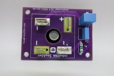
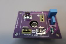
Not to confuse anyone who is using my board, there is no need to raise the rectifier from the PCB with mine since I removed the copper on the bottom side. The info. is for the randy board and not mine. ( and note those are randy boards in the pictures @birdbox is showing. Mine are purple as well and look very similar ) Also note there is no drilling required on mine since the whole is large enough for the bolt head.
- Home
- Amplifiers
- Pass Labs
- Rectifier Snubber Daughterboard - roboDNA