My speakers are smaller than the Summa but I wonder how close these sound compared to the full size Summa (minus the LF extension in the simulations). This is 8 inch freestanding over 8 inch woofer. They miss the mark on the polars by apprx 300Hz if I read the Summa polar data correctly. My simulations are also made at 20 degree listening axis/toe-in.
Something I've noticed is when the speakers are positioned on the long wall of a rectangular room (with unequal side wall distances) the soundstage is only as wide as the speakers. When the speakers are placed on the narrow wall with equal distance to side walls the soundstage is as large as the whole front wall. Yet neither imaging nor intelligibility seem to be damaged despite the larger soundstage width. I also toe them in like Geddes recommends for his speakers. Even though I have extremely limited listening experience I'm convinced Geddes' theories about waveguide sound and positioning are solid => if my speakers are close enough to his that I'm hearing what he gets to hear. This type of waveguide speaker set up the way Geddes describes sounds exceptionally good to my ear.
I have no doubt other designs and setups are good - possibly superior - but Geddes' waveguide way is extremely good when sitting at normal residential listening distances. Of all the choices people have when they setup a system I would recommend this as one of the good options among many good options.
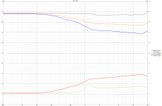
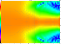
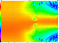

Here are the Summa 20 degree real life non-simulated measurements
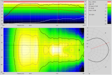
Something I've noticed is when the speakers are positioned on the long wall of a rectangular room (with unequal side wall distances) the soundstage is only as wide as the speakers. When the speakers are placed on the narrow wall with equal distance to side walls the soundstage is as large as the whole front wall. Yet neither imaging nor intelligibility seem to be damaged despite the larger soundstage width. I also toe them in like Geddes recommends for his speakers. Even though I have extremely limited listening experience I'm convinced Geddes' theories about waveguide sound and positioning are solid => if my speakers are close enough to his that I'm hearing what he gets to hear. This type of waveguide speaker set up the way Geddes describes sounds exceptionally good to my ear.
I have no doubt other designs and setups are good - possibly superior - but Geddes' waveguide way is extremely good when sitting at normal residential listening distances. Of all the choices people have when they setup a system I would recommend this as one of the good options among many good options.


Here are the Summa 20 degree real life non-simulated measurements

Last edited:
Ah OK. There's a lot of misinformation about the Klippel drama on ASR
ASR has become a very toxic place thanks to some core members. Disinformation and negativity typically spreads like wildfire there with little interference from the mods unless it’s something bad about the site leader. it’s really weird behavior from adults.
Anyway, glad we got the M2 thing cleared up. 🙂
Oh, forgot to explain the whole reason I started writing that post. Simulation helps as a comparison in case you have measurement problems.
ASR has become a very toxic place thanks to some core members. Disinformation and negativity typically spreads like wildfire there with little interference from the mods unless it’s something bad about the site leader. it’s really weird behavior from adults.
Anyway, glad we got the M2 thing cleared up. 🙂
Yeah it's a bummer. I really and truly think you're doing great work and your dedication to the science is admirable. One of the things that I generally like about scientific forums is that they tend to be free of the drama that plagues all the other forums.
SIDE NOTE:
In case people are just thinking I'm being sycophantic:
Of all the projects I've ever worked on, the 2nd time that I put Unity horns in a car was one of my projects that turned out particularly well. I did something somewhat radical, which was that I put the horns up on the dash, and I used the windshield itself to extend the horn mouth. The idea that I had was that if you got the first 8-12cm right, the rest of the horn could be less than perfect, but it would still (mostly) work like a horn.
This was quite a bit different than what most horn cars were doing in the 90s and in the 00s; in the 90s people were putting horns under the dash of cars, largely because it was a way to put the speakers as far away as humanly possible. In 1995, there were no affordable DSPs and the most famous horn car was owned by a multimillionaire who poured tons of money into his car. He'd literally sold his Ferrari Testarossa to build a car stereo: https://www.racingjunk.com/news/richard-clark-the-buick-grand-national-guru/
Maybe I'm daft, but I got the impression that nearly all of the horn cars were mostly focused on copying Clark's formula, and while it was a very good formula in 1988, by 2004 we had some other options available to us. Particularly because compression drivers were getting very small and DSP was getting very cheap.
So I took the first stab at it in 2006 or so, and then I did it again in 2008, and it was the second design that really shined. I really and truly think it's one of the most successful projects I've ever done.
And then Erin did basically the same thing with some Kef coaxes and my mind was blown.
He's super smart and there's a 99% chance that he came up with all of it on his own, but I got the impression that he was just about the only person that grasped the idea that you can take the entire windshield and turn it into a waveguide. One of these days, Ford or BMW or Mercedes might wake up to this idea, and it's kinda boggled my mind that we don't see this more often:
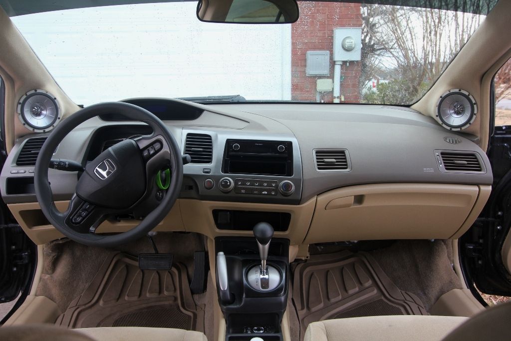
Last edited:
When the speakers are placed on the narrow wall with equal distance to side walls the soundstage is as large as the whole front wall.
In this case, as opposed to long wall, are you sitting further away?
Same distance from the speakers but it places the rear wall (the parallel long wall) closer behind than if I place speakers on the short wall end of the rectangle.
I am not being cynical ... I highly doubt that lol! The designers of Jeep Grand definitely noticed, I have drivers buried in the same corner, turning the corner into a waveguidegot the impression that he was just about the only person that grasped the idea that you can take the entire windshield and turn it into a waveguide.
Array 800 ? 8" + 175nd 1" CD. If I were to build a high output speaker today, it would be a Synthesis 1400 type with 8” woofers instead of the 14” they used.
Array 1000 used a 10".
Actually the 1400 woofers from JBL do better then most in this regard already.
Notice the turncated frame, and how little space there is from the surround edge, to the edge of the frame.
Something not found in most drivers.
Last edited:
But I digress, large systems like the M2 don’t fit modern lifestyles and IME narrow baffle systems image much better. If I were to build a high output speaker today, it would be a Synthesis 1400 type with 8” woofers instead of the 14” they used.
Just purchase a pair of 590's when they go back on sale.
Rob 🙂
I would say the QSC K.2 series are unreliable. A friend bought a pair new and both broke within a year. Many people complaining about reliability. Many pages of common issues in the service manual. I found a blown diode D51 but at first i could not find the type as it was simply marked with a general code KB which seems to be a type of zener. I finally found the actual diode code which is a schottky diode RB751S40T1. Soon after this a technician called me to propose an entire new module. QSC asked an independent tech to call me. He advised me not to try the repair. I briefly quizzed him on the conflicting diode information but he just brushed it off as revisions. But was it the schematic that was revised or the KB diode that was revised on later models, i'm guessing the RB751S40T1 is the latest revision of the KB was fitted by accident?. How can a schottky replace a zener or vice versa? It seems mistakes were made. I'm still confused. Well the first time one of my friends K12.2 blew they fixed it but it took a month via Thomann he uses it only during the ski season which is soon over. This is why i kicked up a fuss on the QSC form and made it public. Seems this time they proposed a faster solution.The QSC waveguide used here is previous gen.
The current QSC K12.2 are interesting....
View attachment 1191467
They top the spinorama chart, even with the KEF Blade meta according to Pierre's site.
https://www.spinorama.org/
Of course it's too good to be true.... The data is heavily smoothed. And the pattern is of course quite narrow.
Nevertheless, you have to give credit to the effort made to smooth all the potential diffraction points.
He is currently contacting the technician to find out if QSC is covering the replacement module at €413 i think it was. This is also confusing to me. The service manual does advise you to check D51. If it ends up being me making the repair i will also de-solder the fets to check them (power supply switching). There is one 6 pin ic (that switches the fets i guess) and i may need to replace this also, but they do not mention it in the service manual although there are literally pages and pages of things known to go wrong. Seems they messed up with this series. perhaps they will rectify these issues but some direct contact with them would have been nice. Anyway although i have 4 QSC power amps i do not feel good about the k2 series so far. Luckily i do not own them myself.
Also, after reading it seems the frequency response depends on the firmware you have installed and how hard you push them depends on what you can get away with.
Last edited:
Someone asked me if I still have the STL files for this.
I probably have them on some old hard drive somewhere, but finding it would likely take hours.
Also, the more that I've messed around with "M2-ish" waveguides, the less aggressive I've made the diffraction slot. Basically, if the surface of the waveguide gets too crazy, the frequency response suffers.
Attached is the latest waveguide that I've made, and it's similar to the one from post 508, but I think the new one should perform better. (The sims definitely look good.)
I've attached the 123D file, which you can open in 123D or Fusion. I've also attached the STL. The model is setup so that you can throw it on your printer, it basically has a raft and some supports built right into the STL file. Obviously, you'll want to cut away the raft and supports after you print it.
It's designed for the SB Acoustics SB19 tweeter, available at Madisound or Meniscus.
It's also a Unity horn; the midranges it's designed for are Tymphany TG9FD. I'm 90% certain that the Tymphany TC9FD should work also.
The file names for the Unity horn version is "Feb 2 2023 cardioid Unity Horn - TG9FD sliced"
I also found a version of the same waveguide that isn't a Unity horn; it's just a plain ol' waveguide.
The file names for that are "Feb 2 SB19 waveguide"
Patrick, I have never tried out a unity horn but I'm not stranger to 3d printing. I'd like to execute on this project for a few reasons:
1. I've never heard nor experimented with a Unity Horn of any type.
2. I have SB19's and a pair of TC9FD's already, for the price of 40 bucks plus my filament I can experiment with these and then if I like the concept I will move on to some of the more high end designs of this type.
3. I'm all active using class D hypex across 8 channels, I'm probably going to set these on top of my enclosures tuned to 50hz that are leverage RS225 8" daytons and that also is driving a pair of corner loaded dual 8" M&K subs and have them run as a 4 way.
4. I use active crossovers generated by Audiolense and convolvers.
Questions:
1. What in general crossovers do you apply to the tweeter and TC9's?
2. What is the overall system sensitivity in the unity horn? At first blush it seems like the TC9's are 83.5 db, doubling them up puts it at 86.5 db, what is the impact of the horn loading to the overall sensitivity?
I know you're a prolific poster and have switched projects frequently so these may have never come to fruition for you to have this info, let me know if I'm barking up a long dead tree here.
In addition, what is your latest and greatest project along these lines so I can follow along? You have a LOT of threads going, it's been a research project lol
Thanks!
John
Is it possible to make a M2 with closed enclosure around 80-100 liter? I dont intend to play very loud. Listening distance will be around 3 meter.
Well, I'd say yes and no. I'd have to simulate it, but the 2216nd isn't on the high side of xmax possibilities, but not the lowest. You'd need to be more specific about spl goals for your 3 meter position. 30hz in a sealed box is possible but I'd recommend doing so in a way that keeps excursion low since the driver has to also play midrange... why not a ported box tuned to 30hz? In a sealed box a 15" is going to start moving considerably at 30hz with significant volume but... lets check an excursion calculator
7.5mm xmax on that driver. This is showing for 1 meter, adding 2 meters to that will lose 6db? So 96db?

7.5mm xmax on that driver. This is showing for 1 meter, adding 2 meters to that will lose 6db? So 96db?
Last edited:
BTW, what's the xmax of the 2216nd?the 2216nd isn't on the high side of xmax possibilities
Here is everything you want to know about them. I have a pair and I can't imagine you having an issue with x max. I would run them ported.
Rob 🙂
https://www.audioheritage.org/vbulletin/showthread.php?33565-2216Nd
Rob 🙂
https://www.audioheritage.org/vbulletin/showthread.php?33565-2216Nd
- Home
- Loudspeakers
- Multi-Way
- JBL M2 for The Poors